


Automatic Gearbox and Torque-converter
Page 64
If you've noticed an error in this article please click here to report it so we can fix it.
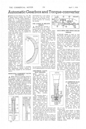
FROM the Ford Motor Co., Ltd., 88, Regent Street. London, WA, comes patent No 632,407, which discloses a design for a three-speed-and-reverse transmission, comprising a torque-converter and an epicyclic gearbox operated automatically by a hydraulic governor. The full action of the unit cannot be explained in a few words, but the main principles can be described in conjunction with the accompanying diagram.
Dealing first with the torque-converter, the engine turns an impeller (1) which drives the output member (2). A reaction runner (3) normally stands still, but can over-run on a one-way clutch to enable the unit to work as a fluid coupling, and so enable the engine to be started by towing .the vehicle.
The output member of t he torque converter
drives the primary shaft (4) of the gearbox, which, by means of clutches (5) can be connected to the output shaft (6) via the various combinations of an epicyclic gear (7). The clutches are hydraulically worked by a pump (8) driven by the output , shaft, and are selected I by a valve worked. by a centrifugal governor, (9). A reverse is provided, and interlocking devices prevent it from being engaged by the automatic system.
PRODUCING COMPOSITE VALVES . BY FORGING •
ANEW method of making-valves by forging a three-piece blank into a homogenous whole, is described in patent -No. 633,964, !by Etablissements E. Dervaux, Paris. The aim is to enable the most favourable materials to be
used for head, seating and stem. •
The blank is initially assembled as shown in the drawing, in which a steel stem (0 ii inserted into a stainless steel head (2). &mild the -head is,placed ring. (3) Made of an alloy containing 80 per cent, nickel and 41 per, cent. chromium. The assembly. is then heated
and forged into a unit, taking care to see that -the nickelchromium ring finishes in the correct position for forming the seating.
THE LATEST IN BIG-END DESIGN
AMEANS for securing a
bearing liner in a connecting rod forms the subject _ of patent No. 633,934, which comes from H. Tryon and D. Napier and Son, Ltd., 211, Acton Vale, London, W.3. The liner referred to is one of the modern type comprising a steel backing strip covered with a layer of bearing alloy.
Referring to the drawing, 1 is part of the connecting-rod end and 2 the liner strip. The bearing is recessed to a precise diameter, and the liner ship is then pressed into place. It is retained by meeting an abutment face (3) at each end of the shell, formed by cutting a longitudinal groove. .Holes (4) are for lubricant, and are present at the middle of the bearing, at which the section shown is taken.
The bearing is said to be particularly suitable for the big-ends of an opposed-piston two-stroke engine,
GRIT-PROOF VALVESEAT GRINDER -F-HE operation of grinding a valve seat calls for the use of sharp abrasives, and it is likely that some of it will find its unwelcome way into the working faces of the tool. To prevent this is the aim of in improved tool shown in patent No. 633,984, by R. McCartney, and the Tartan Manufacturing Co., Ltd., 143-144, Holborn Bars, London, ,E.C.1.
The drawing shows a typical construction in which 1 is the grinding wheel which is carried on a rotary sleeve (2) driven from above via a square or hexagon socket (3). The sleeve runs on a stationary bush (4)
which is held still by its frictional grip on the pilot pin (5), the grip being provided by a split collet erfd (6). The pilot can be changed for ode of another size by simply pulling it out. . As the running bearing is never at any time exposed, it is much less likely that abrasive matter can find its way in. Assembly of the two parts is completed by a steel ring (7) spun over flanges. EXCLUDING DIRT FROM GREASE NIPPLES
GREASE nipples as used on road VI vehicles are usually covered with mud, some of which is bound to find its way into the bearing sooner or later. A scheme for preventing the ingress of dirt in this way forms the subject of patent No. 633,764, which comes from experts in lubrication equipment, Tecalemit, Ltd., and C. LeClair, both of Great West Road, Brentford, Middlesex.
A new type of nipple is used; one of these is shown in the drawing in contact with a grease-gun of the push-on type. The same principle can also be applied, however, to the slide-on or any other type of gun. Dealing first with the nipple, the chief feature is the use of a rubber bush (1) which has a minute hole, normally closed, running thsough it.
To the gun is fitted a spring-loaded slider (2) which, when first applied, .pushes back the rubber flange (3) and so stretches open the entrance to the fine hole. Further movement of the gun advances a taper nose (4) which penetrates the rubber bush and discharges a shot of lubricant therein. When the nose is withdrawn, the rubber bush recloses and forms once again a dirt-proof seal.
AN IMPROVED ELASTIC LOCK-NUT
A POPULAR type of lock-nut is that having a pressed-in fibre washer in its head, the washer being forcibly tapped when the bolt is inserted. According to patent No. 633,961, from the Elastic Stop N u t Corporation of America, Union, New Jersey, U.S.A., the use of fibre as a material is in many ways unsatisfactory. It will absorb up to 50 per cent. of its weight of water, and can, if wet, be pushed out by the entering bolt.
The patent gives details, in highly technical chemical terms, of better materials for the washer. It should be made of "a long-chain synthetic amide having recurring amide groups as an integral part of the main, polymer chain "; this means, in everyday language, nylon.