


MAKING ROAD
Page 46
Page 47
Page 48
If you've noticed an error in this article please click here to report it so we can fix it.
TEHICLE TANKS
for in loads
TII— large road-moLor tanks that maybe seen daily carrying petrol, milk, etc., have become so common that one hardly realizes that extreme care and skill are necessary in the production of such large bodies of comparatively thin metal. Not only are they produced without the slightest unevenness in their outer surfaces, but they have to 'withstand the vibration occasioned by rough roads and the surge of their contents.
With the object of interesting our readers in the methods employed in this recently developed industry, which is closely allied to the motor trade, we have chosen for description the processes of the Steel Barrel Co. (of Uxbridge), Ltd., Phcenix Wharf, Uxbridge, which, beside its other activities, makes a speciality of the production of tanks for road transport.
This company claims to be the originator of what has become known as the low-gravity tank. In its patented design of tank the curve at the bottom is of a larger radius than that of the upper part, slightly
• approaching the form of the letter D. Although a at bottom would reduce still further the centre of gravity, it was found that buckling was likely to take place, so a slight curve was adopted, and is regarded as the company's standard shape of road tank.
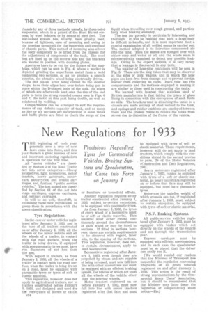
Only best selected British steel plate is used in the manufacture of these tanks, some of which are made to hold as much as 2,500 gallons of petrol, whilst a capacity of 3,000 gallons can be provided for fuel oil. Some tanks are 22 ft. long, 6 ft. li in. wide and 4 ft. 2 ins, high, the gauge of steel varying according to circumstances, the most general thicknesses being is in. and -,A in.
The first process in the manufacture is the pickling of the plates to remove all rust or scale, although, in several cases, the company employs sand-blasting arrangements. After
this they are coated with a temporary protection against rust, which material can easily be washed off, leaving the metal clean and bright, so that any protective coating on the outsideshall have no rust beneath it.
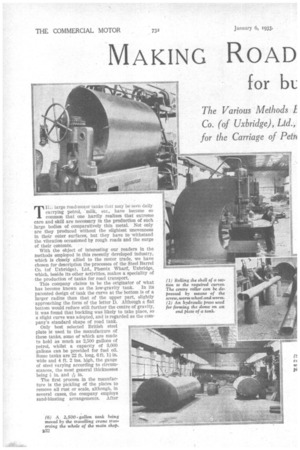
Next, those plates which are to form the body of thetank are bent to the desired curves in the rolling machine shown in Fig. 1, where three rollers will be seen, the uppermost one of which can be depressed by the screw, worm-wheel and worm. More skill isnecessary in this operation than if the tank were circular, as two distinct curves have to be formed, one for the upper part and one for the flatter bottom.
Those readers iivho have had experience in the working of plate metal will realize the difficulty in rolling the cylinders so that their edges come to the exact curves to produce the flush joints seen on these -tanks, because, unless the sections are similarly carved, no flush joint can be made by welding.
The hydraulic press shown in Fig. 2 is employed for making the domes seen on the ends of such tanks. A. fiat end to a tank is not permissible, as, although there is no pressure other than that caused by the weight of the liquid, it has been found that a flat end will buckle, thus causing stresses -in the material. A dome of approximately 3 ins. is, therefore, imparted to the end plates by means of the convex face of the upper tool and the concave face of the under tool used in this press.
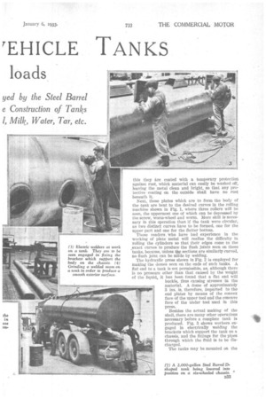
Besides the actual making of the shell, there are many other operations necessary before a complete tank is produced. Fig. 3 shows workers engaged in electrically welding the brackets which support the tank on a chassis, and the fittings for the pipes through which the fluid is to be discharged.
The tanks may be mounted on the
chassis by any of three methods, namely, by three-point suspension, which is a patent of the Steel Barrel concern, by wood bolsters, or by means of steel feet. The last-named system has, latterly, been greatly used, because of lightness, ease of mounting and owing to the freedom permitted for the inspection and overhaul of chassis parts. This method of mounting also allows the body completely to be lifted from the chassis for the adjustment of components of the tank. The steel feet are lined up on the reverse side and the brackets are welded in position with doubling plates.
Apertures have to be cut for the flanges of the manholes, which can be seen in Fig. 4, where a worker is depicted grinding the superfluous metal from a weld connecting two sections, so as to produce a smooth exterior, the abrasive wheel being electrically driven. The end plates, after being curved to the desired shape, have their edges bent over before being put in place within the ashaped body of the tank, the edges , of which are afterwards bent over the rim of the end plate to form the strong rounded corner seen in Figs. 6 and 7, the metal at this part being double, as well as reinforced by welding.
Compartments can be arranged to suit the requirements of any definite capacity of tank, and as many as five or six sections are incorporated in some tanks and baffle plates are fitted to check the surge of the liquid when travelling over rough ground, and particularly when braking suddenly.
The test for porosity is particularly interesting and thorough. It will be realized that such a large body is difficult to handle, and it is most important that a careful examination of all welded seams is carried out. The method adopted is to introduce compressed air into the tank. Then the seams are sponged over with either soap and water or oil, and the whole seam is microscopically examined to detect any possible leakage. Owing to the expert welders, it is very rarely that a leakage is discovered in any tank.
The making of hose-pipe containers will be seen in Fig. 5. These are the long tubes that may be observed at the sides of tank wagons, and in which the hose pipes are kept free from damage and to prevent foreign matter from collecting on them. Each tube has two compartments and the methods employed in making it are similar to those used in constructing the tanks.
We learned with interest that stainless steel of British manufacture is fast taking the place of glass lining in connection with the conveyance of such fluids as milk. The brackets used in attaching the tanks to a chassis are made entirely of steel welded to the tank, and springs and rubber cushions are employed between them and the chassis frame to relieve the tanks from stress due to distortion of the frame of the vehicle.