


Trailer Has Hydraulic Suspension
Page 68
If you've noticed an error in this article please click here to report it so we can fix it.
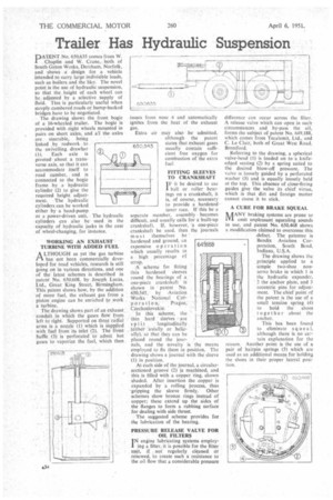
• DATENT No. 650,635 comes from W. Chaplin and W. Crane, both of South Green Works, Dereham, Norfolk, and shows a design for a vehicle intended to carry, large indivisible loads, such as boilers and the like. The novel pointis the use of hydraulic suspension, so that the height of each wheel can be adjusted by a selective supply of fluid. This is particularly useful when steeply cambered roads or hump-backed bridges have to be negotiated. The drawing shows the front bogie of a 16-wheeled trailer. The bogie 'is provided with eight wheels mounted in pairs on short axles, and all the axles are steerable, being
linked by rodwork to
the swivelling drawbar (1). Each axle is pivoted about a transverse axis, so that it can accommodate itself to road camber, and is connected to the bogie frame by a hydraulic cylinder (2) to give the required height adjustment. The hydraulic cylinders can be worked either by a hand-pump or a power-driven unit. The hydraulic cylinders can also be used in the capacity of hydraulic jacks in the case of wheel-changing, for instance.
WORKING AN EXHAUST TURBINE WITH ADDED FUEL
A LTHOUGH as yet the gas turbine I—% has not been commercially developed for road vehicles, research is still going on in various directions, and one of the latest schemes is described in patent No. 650,608, by Joseph Lucas, Lid., Great King Street, Birmingham, This patent shows how, by the addition of more fuel, the exhaust gas from a piston engine can be enriched to work a turbine.
The drawing shows part of an exhaust; conduit in which the gases flow, from left to right. Supported on three radial arms is a nozzle (1) which is supplied with fuel from its inlet (2). The front baffle (3) is perforated to admit hot gases to vaporize the fuel, which then
'ssues from nose 4 and automatically ignites from the heat of the exhaust gas.
Extra air may also be admitted, although the patent states that exhaust gases usually contain sufficient free oxygen for combustion of the extra fuel.
FITTING SLEEVES TO CRANKSHAFT
IF it be desired to use I ball or roller bearings on a crankshaft, it is, of course, necessary to provide a hardened inner race. If this be a separate member, assembly becomes difficult, and usually calls for a built-up crankshaft. IL however, a one-piece crankshaft be used, then the journals must themselves be ' •
hardened and ground, an expensive operation which usually results in a high percentage cf scrap, • 'A scherne for fitting thin hardened sleeves round the bearings of a one-piece crankshaft ' is shown in patent No. 650.545; by -Aviation Works National Cofporatio n;• 'I Prague, Ciechoslovakia.
In this scheme, the thin hard sleeves are
split longitudinally, (either ''axially or helically), so that they can be placed round the jour nals, and the novelty is he means employed to fix them in position. The drawing shows a journal with the sleeve (I) in position.
At each side of the journal, a circularsectioned groove (2) is machined, and this is filled with a copper ring, shown shaded. After insertion the copper is expanded by a rolling process, thus .gripping the sleeve firmly. Other schemes show bronze rings instead of copper; these extend up the sides of the flanges to form a rubbing surface for dealing with side thrust.
The suggested scheme provides for the lubrication of the bearing.
64I8s PRESSURE RELEASE VALVE FOR OIL FILTERS TN engine lubricating systems employ' ing a filter, it is possible for the filter unit, if not' regularly cleaned, or renewed, to create such a resistance to the oil flow that a considerable pressure
difference can occur across the filter. A release valve which can open in such circumstances and by-pass the oil, forms the subject of patent No. 649,188, which comes from Tecalemit, Ltd., and C. Le Clair, both of Great West Road. Brentford.
Referring to the drawing, a spherical valve-head (I) is loaded on to 'a knifeedged seating (2) by a spring suited to the desired blow-off pressure. The valve is loosely guided by a perforated washer (3) and is equally loosely held at the top. This absence of close-fitting guides give the valve its chief virtue, which is that dirt and foreign matter cannot cause it to stick.
A CURE FOR BRAKE SQUEAL
14ANY braking systems are prone to LVL emit unpleasant squealing sounds in use, and patent No. 650,468 shows a modification claimed to overcome this
• defect. The patentee is 13endix Aviation Corporation, South Bend, Indiana, U.S.A.
The drawing shows the principle applied to a simple two-shoe nonservo brake in which I is the hydraulic expander, 2 the anchor plate, and 3 eccentric pins for adjustment. The chief point of the patent is the use of a small tension spring (4) to hold the shoes together about the anchor.
This has been found to eliminate squeal. although there is no certain explanation for the reason. Another point is the use of a pair of hairpin springs (5) which are used as an additional means for holding the shoes in their proper lateral position.