


Fully Freeable Fluid Clutch
Page 40
If you've noticed an error in this article please click here to report it so we can fix it.
A Résumé of Recently Published Patent Specifications
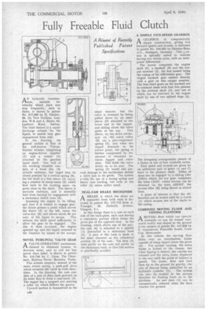
AN hydraulic transmis sion, suitable for vehicles which start and stop frequently, such as Mises, is shown in patent No. 517,989 by H. Sinclair, 38, De Vere Gardens, London, W.8, and A. Basbe, 52, Lambert Road, Sutton. The chief feature. is a rapiddischarge scheme for the liquid, to enable easy gear engagement from rest.
In the drawing, the general outline is that of the well-known VulcanSinclair scheme, comprising an engine-driven impeller (7) and a runner (1) attached to the gearbox input shaft. One wall of the working chamber consists of a loose disc (3) slidable endways, but urged into its closed position by a central spring (6). On the shaft is a free sleeve (5) carrying a number of scoop-tubes (2) which lead back to the working space via ports close to the shaft. The sleeve is movable endways, and is normally held from turning by engagement with a stationary clutch cone (4).
Assuming the engine to he idling, and that it is wished to engage gear, the driver presses a pedal which moves the sleeve (5) to the left, opens the valve-disc (3) and allows about 80 per
cent, of the liquid to escape. This reduces the shaft speed sufficiently to allow the gear to be engaged. The disc is then re-closed, the engine speeded up, and the liquid returned to the chamber by means of the scoops.
NOVEL PUSH-PULL VALVE GEAR
AVALVE-OPERATING mechanism, claimed to eliminate bounce, to decrease noise, and to call for less power than usual, is shown in patent No. 516,746 by C. Glass, The Chestnuts, Railway Street, Beverley, Yorks.
This scheme employs, instead of the usual return spring, a push-pull drive which actuates the valve in both directions. In the drawing, the cam consists of a pair of discs each grooved on its inner face to form a cam-track (5). The tappet has a tongued end carrying a roller (4) which follows the groove.
Upward motion is transmitted in the usual manner, but the valve is returned by being pulled down by an outer sleeve (3) attached at the lower end to the tappet, and sliding about the valve
guide at the top. This sleeve, on the down stroke, acts on the valve collar (2) via a pre-compressed spring (1) and when the tappet descends to its lowest point, the spring ia further compressed by the amount of clearance between tappet and valve stem. This holds the valve firmly on to its seat. The spring (1) would also prevent damage to the mechanism should a valve jam in its guide. The system avnids the use of a strong spring and heavy cam loading, but evdn so the roller (4) seems rather small.
DUAL-CAM BRAKE MECHANISM
ABRAKE in which the shoes are expanded from both ends is disclosed in patent No. 517,712 from A. Younger, 26, Dalkeith Avenue, Glasgow, 5.1.
In this design there is a cam on each side of the hack-plate, each cam having a concentric portion which forms the pivot pin of the opposite shoe. In the drawing, which shows one of the pair, the cam (I) is attached to a spindle (1) journalled in a stationary bush (5). A part of this bush is made to the same diameter as the cylindrical portion (3) of the cam. The shoe (2) rests partly on the cam and partly on the stationary bush, so that lost motion is practically avoided. A SIMPLE FIVE-SPEED GEARBOX A GEARBOX of comparatively ti simple construction, giving five forward speeds and reverse, is disclosed in patent No. 516,885 by Daimler-Benz A.G., Stuttgart, Germany. —This parbox is is specially suited to vehicles having two driven axles, with an interposed differential.
The layout comprises the engine shaft (5), a layshaft (3) and the output member (2), the last named being the casing of the differential gear. The largest layshaft gear meshes directly with a gear on this output member. The four fixed gears on the layshaft are in constant mesh with four free pinions on the primary shaft (5), any one of which can be clutched to the engine shaft by one of two splined dogs (4).
The foregoing arrangements permit of a choice of one of four available ratios.
First speed and reverse are given by an additional pair of gears (A and C) fixed to the primary shaft. Either of these can be engaged by a sliding idler (DEG) which, for low gear, completes the train CDGF, whilst reverse can be obtained via the train ABDEF, the reverse idler (B) being shown in dotted lines.
A point of interest is that the differential can be locked solid by a clutch (1) which secures one of the shafts to the casing.
COMBINED MOVING FLOOR AND TIPPING PLATFORM
A MOVING floor which can operate
normally or can be wound rearwards bodily and sloped to the ground is the subject of patent No. 517,828 by F. Greenwood, Ferncliffe South, Cross Cop. Morecambe. In this scheme the moving floor slides over an intermediate frame capable of being tipped about the pivot (3). For normal running, the extra frame is locked' to the chassis, but when tipping is desired, the catches are released and the extra frame displaced to the rear until the point of balance is passed. The frame, floor and load then tip to the ground by gravity, the rate of descent being controlled by an hydraulic cylinder (2).. The system can also be worked in the .reverse direction for hauling loads on to the
platform. An end door (1) can be automatically released when the floor touches the ground.