


Patents Completed.
Page 24
If you've noticed an error in this article please click here to report it so we can fix it.
Another Detachable Rim.
E. F. Goodyear and G. W. Goodyear.— No. 25,747, dated 18th November, 1911, Patent of Addition to No. 5340 of 191L— In this wheel, the felloe is made of chan
nelled section with one flange smaller than the other. A number of bolts are arranged transversely in the channel, and these are connected to gripping or wedging members which are pulled by the screws underneath the smaller flange and the detachable rim when it is In place. A particular feature of this invention is that the gripping member is swivelled on a roller which is operated by the bolts. When the gripping members are withdrawn, they are moved across the channel until their inner ends meet the high flange of the rim. This holds them so that they do not offer any obstruction to the replacement of the detachable rim.
A Cam-controlled Carburetter.
Clement Brown, and Brown and Barlow, Ltd.—No. 17,203, dated 27th July, 1911.—The air from the main-air inlet enters the passages shown at the righthand side and passes two jets on its way to the cylindrical throttle-valve, which is divided into two parts by a sloping partition. The lower half controls the main-air and mixture, and the upper half controls the auxiliary air which enters the valve chamber through a springcontrolled valve at the top. The jets are preferably of the type in which a jet -orifice, supplied from a float chamber, is controlled by an eccentric or rotating cam, the orifices being covered and uncovered by the edge of the cam as it is rotated. This arrangement of jets is stated to be suitable for working under load, but for slow running an auxiliary by-pass having a separate jet is provided. This communicates with the engine side of the throttle, the air for this
by-pass being taken in by a separate inlet. The carburetter described has two variable jets in addition to the by-pass. They are adapted to open successively in accordance with engine. demand.
Improved Radiator Construction.
T. H. Harris.—No. 25,665, dated 17th November, 1911.—A radiator is built up of top and bottom reservoirs or tanks,and a number of detachable cooling elements which are arranged in the usual way between the tanks, but are carried by an independent external frame which also carries a main water tank. The accompanying drawing shows in section the main water tank, the upper header, and the arrangements for allowing the passage of water from the main tank through the header into the radiator tubes. Tapered plugs are soldered or brazed into the two water tanks, and these are perforated round the side to permit the water to pass from one to the other, the header being
held hi place by screws passing through it and into the plug in the main tank. A long, tapered, perforated tube is connected by a rubber tube to the bottom of the header, and extends inside the radiator tube. This is fixed at the other end by a screw passing through a suitablypacked thimble.
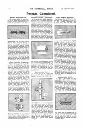
An Accessible Brake.
J. Weller, No. 25,505, dated 15th November, 1911.—The accompanying illustration shows a brake which is speci ally suitable for use on steering wheels, but which can, of course, be applied to any wheel which has a non-rotating axle. A brake-drum, preferably of the internal type, is fitted on the outside of the wheel, or, if within the plane of the wheel, is arranged with its open side facing outwards. The brake member is carried on the outer end of the stubaxle; this is squared to prevent its turning. The axle is drilled through its length, and the brake member is controlled by a flexible cable passing through it.
Novel Wolseley Springing.
The Wolseley Tool and Motor Car Co., Ltd., and A. A. Remington.—No. 16,879, of 1911, Cognate Application No. 25,419/11, dated 24th July, 1911.—The springs on the road wheels of a van are arranged to have a quicker periodicity when the van is rolling than when the whole body is moving vertically compared with the axle. An ordinary leafspring is fixed at the middle on a transverse shaft on the chassis, and is connected at its rear end with the wheel axle through a link, and at the forward end with a bracket on the frame, also through a link. If both springs are affected equally, that is, if the axle receives a shock which moves both ends equally, the transverse shaft turns slightly in its bearings and allows the full elastic capacity of the springs to be used. If, on the other hand, the van is rolling, one end of the axle is raised and the other lowered so that the two springs tend to turn the transverse shaft in opposite directions and it therefore remains stationary. The elasticity on the springs in this condition is confined to the rear half only. There is also described the application of supplementary shock absorbers for connecting the forward end of the springs to the chassis to take up small shocks which would not readily be absorbed by the main springs.
Standardizing Wheels.
E. B. Killen.—No. 19,099, dated 25th August, 1911.—This invention has for its object the provision of an attachment for wheels by which wheels varying slightly in diameter and in width, as is usually the case, are readily adapted to receive standard tires. An auxiliary rim built up in segments is secured to the felloe by a flange extending inwardly, and is gripped by bolts passing through the felloe. This extra rim is made consider
ably wider than the ordinary rim, in order to accommodate the standard size of solid tires, and also project a little more on each aide, so that the tires and the wheel itself are protected from kerb and other shocks.