


Adapting a Lorry to Track Drive
Page 68
If you've noticed an error in this article please click here to report it so we can fix it.
AN A N attachment for temporarily converting a lorry to an endless-track vehicle is described in patent No. 656,680, by B. Symes, East Hyde Farm, Tillingham, Essex. The scheme is novel • in that the track lies entirely under the wheels instead of surrounding them in the usual way.
• The drawing illustrates the attachmein (1) which consists of an endless
band, suitably treaded, mounted on its own self-contained bearings carried on side-plates. The units can be laid on the ground, the vehicle run on to them, -and then secured by chains and stirrup members (2) fitted to suit the particular vehicle employed. The method reverses the direction of the drive, as it really interposes an idler, but the low reverse gear of the average vehicle is considered to be quite suitable for the circumstances in which the attachment would be used.
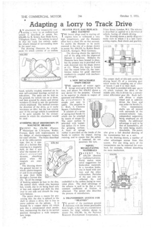
'AVOIDING HEAT DISTORTION IN MAGNETIC BRAKES
DATENT No. 656,308 (Electro1 Tvfecanique de L'Aveyron, Rodez, France), deals with improvements in the design of electro-magnetic brakes for road vehicles. The brake described is of the eddy-current
type, that is, it consists of a ferrous disc rotating in a magnetic field, so that it acts after the manner of a short-circuited dynamo, absorbing power when the magnets are energized.
The drawing shows the general lay-out in which electro-magnets • (1 and 2) are arranged to pass their fields through a ferrous disc (3). As all the energy of braking appears as heat in the disc, the central shaft, which also becomes hot, would, due to its being fixed only at 'one end, expand and shift the disc over to one side and disturb the magnetic balance.
The patent shows a means for preeating this; the disc is splined to the shaft to obtain a drive, but is free to • move endwise on the splines. it is • located by a copper sleeve (4) which acts like a compensated clock pendulum, maintaining the disc in its•central position throughout a wide temperature range.
A38
HEATER PLUG HAS REPLACEABLE ELEMENT
THE heater plugs used in starting oil engines have to withstand a very high tempdrature, and the filaments
often have a short life on that account.
To enable the filament to be easily renewed is the aim of a design shown in patent No, 656,339, by Robert Bosch G.m.b.H., Stuttgart, West Germany.
The drawing shows the operative end of the plug with the ,improved filament in position. Hitherto the filaments have been brazed in place, but the present one is provided with ends distorted into the shape shown at (1). When this form is forced into the round holes (2), the interference makes for good electrical conductivity coupled with rnechanical strength.
A NEW DETACHABLE SNOW-TREAD
THE approach of winter again
brings snow-grip devices to the fore, and paten/ No. 656,912 shows a new device for the purpose. Claimed to be superior to chains in respect of quietness and efficiency, the attachment is simple and easy to apply. The patentee is C. Rich, 5, Clarence Square, Cheltenham.
• It consists of a series of spring-steel bands (I) which can be attached by means of straps (2). The outer surface is Provided with 'numerouS spikes (3) to form the gripping surface.
A layer of sponge rubber is provided on the inside of the bands to cushion the impact during running, and to ensure that the spikes if loosened, donot penetrate the tyre.
NOVEL' BRAKE-FACING MATERIALS
PATENT No. 656,324 (Societe Le Carbone-Lorraine, Paris) makes some novel suggestions for brake-shoe materials. in a two-shoe brake, one is faced with cast iron and the other with-carbon. Particles of the cast iron are collected .by, and embedded in the carbon facing as wear takes place. The chief advantage of the scheme is said to be that a very constant coefficient of friction is obtained. The patent also describes the process of manufacture.
A TRANSMISSION SYSTEM FOR "HEAVIES"
TO permit of the maximum ground clearance with the lowest practicable floor height, is the aim of a transmission system. for Jarge vehicles shown in patent No. 656,586, by the National Research Development Corporation, I.
Tilney Street, London, W.1. The scheme is described as applied to a six-wheeled vehicle, having all wheels driving.
The drawing shows a partly diagram-. matic view in which 1 is a unit representing engine, fluid clutch and gearbox:
The output shaft of this unit carries the driving bevel (2) of a reversing gear which works by coupling one or other of bevels 3 and 4 to their shaft.
This shaft is provided with spur gears (5) which transmit the drive to the middle axle; this is driven Via a conventional differential gear (6). Each half axle drives a single h5639 wheel and in addition drives the front and rear axles via bevels (7).
The transmission shafts are all jointed with universals of the constant-velocity type, independent suspension being employed on all wheels. An additional advantage is said to be that of accessibility, all the units being readily detachable. The patent also gives a full detailed drawing of the transmission box as a unit.
As the drawing shows, a number of other advantages accrue from this system. For one thing, parts of the transmission can be removed for overhaul, for example, without disturbing the main mechanism.