


Sprin brakes: let's dispel the myths
Page 42
Page 43
Page 44
Page 45
Page 46
If you've noticed an error in this article please click here to report it so we can fix it.
WHEN talking to heavy vehicle operators and, more particularly, workshop staff, it is surprising to discover how many myths and suspicions still surround spring brakes and their applications.
One supposes that their history of approximately 10 years in the UK and Europe is relatively short for the traditionally conservative transport industry; and horrific tales of ill-considered tampering, that led to parts of spring brake units disappearing at great velocity across the workshop, are still related with nervous amusement and are, undoubtedly, the root of unjustified anxiety.
Manufacturers have always been careful to emboss warnings on the body of brake units and have placed great emphasis on safety aspects in service literature. But it seems that, in many cases, the cautions have only served to make fitters even more doubtful.
History of spring brakes
Like air braking for heavy commercial vehicles in general, spring brakes have their origins in the USA. As gross vehicle weights and, therefore, foundation brake sizes increased, it became necessary for drivers to be able to exert higher and higher forces on handbrakes in order to park and safely hold a fully laden vehicle.
Eventually, simple linkages became impractical and sundry power-assisted devices rather complicated. Spurred on by a rash of newsworthy runaways on those much-filmed, hilly streets of San Francisco, the fail-safe spring brake was developed in the late 1950s.
It was termed fail-safe because air pressure was used to hold the brakes off, and in the event of a sudden loss of reservoir pressure or for parking, air was exhausted and powerful compression springs applied the brakes.
Spring brakes were introduced to Europe in the late 1960s and, although the basic operating principles were and still are as already .described, their installation into the total air system was quite different.
In the US, until recently, spring brakes have been solely for parking and simple on /off emergency braking, but in Europe, they were called on to provide progressive secondary braking as well.
Instead of the two-position parking button or lever facing the American driver, the British driver had a hand valve or 'deadman' with which he could vary the rate of air loss from the spring brakes and, therefore, apply the brakes in a controlled manner. The presence of this hand valve led to many of the problems with spring brakes when they first appeared in Europe.
Drivers with a tired right foot could not resist the temptation to play with the lever and use the secondary brake in place of the service brake. This caused many spring breakages then and is still responsible for considerable shortening of spring life now.
Spring brake designs The various types of spring brake may be defined as follows: 1 Piston; a) conventional; b) reversed. 2 Diaphragm; a) rolling; b) standard.
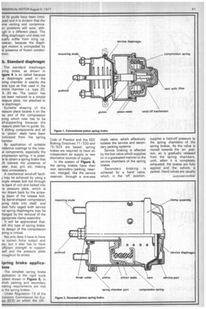
la. Conventional piston
The conventional piston spring brake is shown in Figure 1. Service braking is achieved by a standard diaphragm as in the simple single diaphragm air chamber. Attached to the back is the spring chamber, usually an aluminium diecasting, which contains the powerful compression spring, which is, itself, contained by a piston sliding in a machined bore.
Spring force is transmitted via a pushrod carrying a plate that bears on the service diaphragm. Air pressure, acting on the piston, holds the spring retracted for, normal running, allowing the service diaphragm to function in the usual way.
As air is exhausted from the spring chamber, the piston is pushed down its bore by the compression spring which is then applying the brakes via the pushrod bearing on the service diaphragm.
To cater for those occasions when air is not available and for changing of the service diaphragm, a mechanism is usually built into the spring chamber to allow the compression spring to be wound off and safely retained.
And if the device is to work at all, the area around the spring must be vented. So, it is necessary to provide a breather, which must also contain a filter to keep out contaminants.
1 b. Reversed piston spring brake
Basic' operating principles are the same for this unit except that, as may be seen in Figure 2, the layout is r,eversed with the spring chamber providi the spring brake mounting fa and the service chamber slu on the rear. Main spring force transmitted from the piston the pushrod via a thrust col on the pushrod.
A spring wind-off mechE ism is not easily incorporated this design, though for servi diaphragm changes it is r necessary, because the servi chamber may be readily a safely dismantled witho touching the spring chamt part of the unit.
It is only the hopefully-ra event of total air failure th could lead to embarrassmer for, without air, all sprii brakes would be on and there no way of mechanically cagir the springs to allow z obstructing vehicle to be tom away.
2. Diaphragm sprin brakes
In order to overcome ti inherent disadvantages of tl piston spring brake, the last 1 years have seen the develo ment of two basic designs diaphragm spring brake.
By definition, a piston sprir brake consists of a pistc sliding along a bore in chamber which has to t adequately vented, but whic also must be kept absolute clean if the piston seals are 1 remain intact and have reasonable life.
Assuming the "perfect filte may be found to elinninai completely all traces of wate dust, grit etc, from the incorr ing air, there is always th inevitable problem of conder sation forming in the chambe leading to corrosion of intern; components and icing up i winter.
The object of a diaphragr spring brake is to eliminate th piston and machined bore thereby removing the problem of wear, contamination condensation.
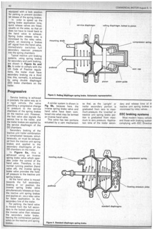
2a. Rolling diaphragm
As may be seem from Figur 3, the rolling diaphragm brak is something of a compromis between piston and diaphragm The 'piston' no longer run in a bore, but has a specie diaphragm attached which i, retained at its periphery by ; conventional clamp assembly As the "piston' moves along it guide, this diaphragm has rolling motion, hence the nam( 'rolling diaphragm.'
"While the vulnerable pistor seals have been eliminated new seals between the "piston ld its guide have been introiced and it is evident that the ime venting and contaminaDn problems still exist, althugh in a different place. The lling diaphragm unit does not sually suffer from icing up, nwever, because the diaphigm motion is unimpeded by ie presence of frozen condention.
b. Standard diaphragm
The standard diaphragm coring brake, as shown in igure 4 is so called because te diaphragm used in the pring chamber is exactly the ame type as that used in the ervice chamber i.e. type 20, 4, 30 etc. The 'piston' has ow been reduced to a simple ressure plate, not attached to diaphragm.
Suitable shaping , of the ressure place locates it on the .ee end of the compression pring which now has to be elf-supporting because the ressure plate has no guide. So, II sliding components and all le 'piston seals have been liminated from the spring hamber.
By application of suitable rotective coatings to the interal components, especially the ompression spring, it is possile to obtain a spring brake that /ill tolerate the presence of /ater, dust, grit, etc, making Iters unnecessary, A mechanical wind-off facili/ may be achieved by using a imple release bolt fed through le back of unit and locked into le pressure plate, which is -len drawn back by the screw down of the release bolt. ite barrel-shaped compression pring folds into itself, and /hen fully caged both service nd spring diaphragms may be hanged by the removal of the ppropriate clamp assembly.
It will be appreciated that, with this type of spring brake, he design of the compression pring is critical.
Not only does it have to have "le correct force output and 3te, but it also has to have ufficient strength to support self and the pressure plate -ifoughout its stroke.
:pring brake applicaions
The simplest spring brake pplication is the rigid truck ystem shown in Figure 5, in vhich parking and secondary iraking requirements are met iy the spring brakes.
Under Regulation 13 of the :conomic Commission for Euripe (ECE) on which the UK
Code of Practice and the EEC Braking Directives 71/320 and 75/524 are based, spring brakes are required to have an independent air supply or two alternative sources of supply.
In the system of Figure 5, the spring brakes have their own secondary/parking reservoir, charged, like the service reservoir, through a one-way check valve, which effectively isolates the service and secondary parking systems.
Service braking is effected by the foot valve which supplies air in a graduated manner to the service chambers of the spring brakes.
Secondary braking is achieved by a hand valve, which, in the 'off' position, supplies a hold-off pressure to the spring chambers of the spring brakes. As the valve is moved towards the 'on' position, air is gradually released from the spring chambers, until, when it is completely exhausted, the brakes are fully applied and the vehicle is parked. Hand valves are usually equipped with a lock position for parking to prevent accidental release of the spring brakes.
In order to speed up the spring brake application time, quick release valves are fitted, usually on the axles, so that air does not have to travel back to the hand valve to exhaust. Spring brake release time is minimised by the relay valve, which, on receiving a 'brakes off' signal from the hand valve, immediately switches full secondary reservoir pressure into the spring chambers.
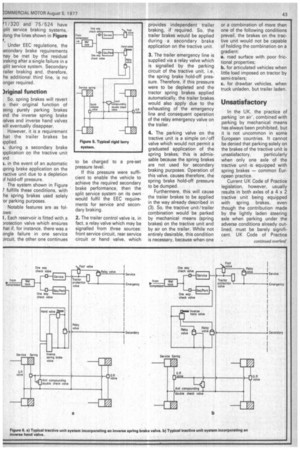
Typical tractive unit braking systems, using spring brakes for secondary and park braking, are shown in Figure 6a and 6b. In order to comply with the UK Code of Practice regulations, the trailer must have secondary braking via a third line; this, normally, is achieved by usMg double diaphragm (DD) brake chambers on the trailer.
Progressive
Service braking is achieved in precisely the same way as in a rigid vehicle, the valve providing a progressive change in pressure to the service chambers of the spring brakes on the tractive unit. However, the foot valve also signals the service line to the trailer, and the trailer brakes are applied by the service diaphragm of the DD chambers.
Secondary braking of the tractive unit trailer combination is complicated because, simultaneously, air must be exhausted from the tractive unit spring brakes and applied to the secondary diaphragms of the DD chambers on the trailer.
In Figure 6a, this is aohieved using an inverse spring brake valve which operates under the control of the hand valve. Therefore, in the normal running position (hand valve off), the inverse spring brake valve provides the holdoff pressure to the tractive unit spring brakes.
As the hand valve is moved towards the full secondary braking or 'on' position, the inverse • spring brake valve simultaneously releases air from the tractive unit spring brakes and applies air, via a relay valve for faster application, to the secondary line of the trailer. .
For parking, the hand valve is moved from the full secondary to the locked position and the inverse valve then releases the secondary trailer brake, leaving the combination parked solely on the tractive unit spring brakes.
A similar system is shown in Fig 6b, because here, the inverse spring brake valve and hand valve have been combined into what may be termed an inverse hand valve.
This valve has two portions actuated. by a cam mechanism so that, as the 'upright' or trailer secondary portion is graduated from zero to maximum pressure, the 'inverted' or tractive unit spring brake portion is graduated from maximum to zero pressure. Application time of the trailer secon dary and release time of tractive unit spring brakes minimised by relay valves.
EEC braking systems
Most modern heavy vehicIE and those with braking system complying with EEC DirectivE 1/320 and 75/524 have plit service braking systems, long the lines shown in Figure Under EEC regulations, the econdary brake requirements 'nay be met by the residual praking after a single failure in a iplit service system. Secondary :railer braking and, therefore, he additional third line, is no onger required.
3riginal function So, spring brakes will revert o their original function of Peing purely parking brakes ind the inverse spring brake valves and inverse hand valves Mil eventually disappear.
However, it is a requirement hat the trailer brakes be
1. during a secondary brake 3pplication on the tractive unit )nd
). in the event of an automatic ;pring brake application on the ractive unit due to a depletion Pf hold-off pressure.
The system shown in Figure 7 fulfills these conditions, with :he spring brakes used solely or parking purposes.
Notable features are as folows: 1. Each reservoir is fitted with a Protection valve which ensures :hat if, for instance, there was a ;ingle failure in one service :ircuit, the other one continues to be charged to a pre-set pressure level.
If this pressure were sufficient to enable the vehicle to achieve the required secondary brake performance, then the split service system on its own would fulfil the EEC requirements for service and secondary braking.
2. The trailer control valve is, in fact, a relay valve which may be signalled from three sources: front service circuit, rear service circuit or hand valve, which provides independent trailer braking, if required. So, the trailer brakes would be applied during a secondary brake application on the tractive unit.
3. The trailer emergency line is supplied via a relay valve which is signalled by the parking circuit of the tractive unit, i.e. the spring brake hold-off pressure. Therefore, if this pressure were to be depleted and the tractor spring brakes applied automatically, the trailer brakes would also apply due to the exhausting of the emergency line and consequent operation of the relay.emergency valve on the trailer.
4. The parking valve on the tractive unit is a simple on /off valve which would not permit a graduated application of the spring brakes; this is admissable because the spring brakes are not used for secondary braking purposes. Operation of this valve, causes therefore, the spring brake hold-off pressure to be dumped.
Furthermore, this will cause the traiier brakes to be applied in the way already described in (3). So, the tractive unit/trailer combination would be parked by mechanical means (spring brakes) on the tractive unit and by air on the trailer. While not entirely desirable, this condition is necessary, because when one or a combination of more than one of the following conditions prevail, the brakes on the tractive unit would not be capable of holding the combination on a gradient: a. road surface with poor frictional properties; b. for articulated vehicles when little load imposed on tractor by semi-trailers; c. for drawbar vehicles, when truck unladen, but trailer laden.
Unsatisfactory
In the UK, the practice of parking 'on air', combined with parking by mechanical means has always been prohibited, but it is not uncommon in some European countries. It cannot be denied that parking solely on the brakes of the tractive unit is unsatisfactory, particularly when only one axle of the tractive unit is equipped with spring brakes — common European practice.
Current UK Code of Practice legislation, however, usually results in both axles of a 4 x 2 tractive unit being equipped with spring brakes, even though the contribution made by the lightly laden steering axle when parking under the adverse conditions already outlined, must be barely significant. UK Code of Practice regulations concerning gradient parking ability are, in fact, more stringent than the EEC 71/320 requirements as shown in Table 1.
It can be seen that neither piece of legislation takes account of adverse road surface or loading conditions.
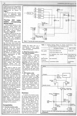
Two-line EEC trailer system incorporating spring brakes
One possible solution to this dilemma, which would also eliminate the contentious issue of parking 'on air' is shown in the trailer braking system depicted in Figure 8.
Notable features are that the normal relay emergency valve has been replaced by a simple relay valve, the emergency function now being handled by the spring brakes.
During normal trailer braking, the relay valve would be signalled by the service line and air would be switched from the reservoir into the service chambers of the spring brakes, via load-apportioning valves, essential for compliance with the tractive unit trailer compatibility requirements of EEC Directive 75/524.
Automatic trailer brake application, after severance of the emergency line, would be provided by the spring brakes, which contain their hold-off pressure directly from the emergency line via the shunting valve.
This valve is used for yard shunting or similar operations, when it is necessary to move the trailer without connecting the air lines. On depression of the button, air is switched from the trailer reservoir into the spring chambers of the spring brakes which are then released.
An automatic reset feature is built in so that, when the air lines are next connected, the shunting valve returns to its rest position of supplying hold-off pressure from the emergency line to the spring brakes.
The double check valve has an anti-compounding function, and the holding quick release valves prevent any movement of the spring brakes until the emergency line pressure has fallen below a predetermined level, making them unresponsive to transient fluctuations in emergency line pressure.
Compatibility 1. Two-line tractive units
As far as current two-line tractive units are concerned, a trailer equipped with this spring brake system would behave in exactly the same way as a conventional two-line trailer, and, therefore, compatibility would be preserved.
2. Three-line tractive units — UK Code of Practice.
Compatibility between three-line tractive units and two-line trailers is always a problem. A simple solution here would be to provide a 'dummy' secondary line as shown in Figure 8 this also being capable of signalling the relay valve and, therefore, applying the trailer brakes. This 'dummy' line would be left open when connecting the two-line tractive units.
3. EEC tractive units An EEC tractive unit employing the system of Fig 7 would be totally compatible with this spring braked trailer, with the added advantage that a spring brake application on the tractive unit would trigger a spring brake application on the trailer, and, therefore, the whole combination would be positively parked by mechanical means.
Summary A review of currently available spring brakes showed that the standard diaphragm spring brake has the most to offer in terms of operational advantages, having effectively eliminated the inherent problem areas associated with other designs. It was observed, however, that the compression spring design is extremely critical with this unit, if acceptable spring performance and diaphragm life are to be obtained.