


Show Atkinsons have Cummins and Improved Cab
Page 77
Page 78
Page 79
If you've noticed an error in this article please click here to report it so we can fix it.
THERE will be considerable interest in two newly designed vehicles to be exhibited by Atkinson at the Commercial Motor Show. Both are tractive units designed to operate at the increased gross train weights allowed by the Construction and Use Regulations and have Cummins engines. Also of interest will be the braking system on these two chassis, which is Atkinson's answer to the problems of improved braking posed by the new regulations and will be the standard system used by the concern. On one of the chassis a new design of cab is fitted.
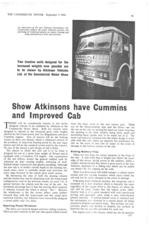
The chassis to which this new cab is to be fitted is designed for use at a gross train weight of 30 tons and is equipped with a Cummins V-8 engine. The construction of the cab follows closely the general method used by Atkinson on their existing models, consisting of steelflitched timber framework and plastics panelling. Although the new cab is of similar overall depth to the existing one, much . more room is available inside and provision for entry steps forward of the wheels gives easier access.
By decreasing the rake of both the steering column and the windscreen, and by dispensing with the wrap-round configuration used in the previous model, an extra 7 in. is gained between the column and the rear of the cab. An incidental advantage here is that the steering effort required is reduced, because the wheel is almost "flat ". Because the windscreen is flat . the corner pillars come farther forward than with the wrap-round and this could have restricted visibility, but Atkinson have successfully designed a comer pillar only 3 in. thick.
Opening Panel Windows The doors are forward hinged and have sliding windows. There are also windows in the rear side panels which extend from the door jamb to the rear corner post. These are of the balanced-drop type and the driver can use the one on his side for putting his head out when reversing. the opening in the door window being fairly small and permitting hand signals only to be made out of it. The more conventional entrance-over-the-wheel design is available with this cab, where an operator has preference for this on the score of less cost of repair in the event of damage to the bottom corners of the cab.
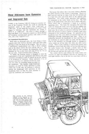
Sliding Battery Tray There are two flaps for access purposes at the front of the cab. A full-width flap is hinged just below the lower edge of the screen, giving access to the radiator, whilst a smaller, bottom-hinged flap below it gives access to the four batteries, mounted on a sliding tray which can be pulled out about 5 in. for topping up the cells.
There is a three-piece full-width bumper, a robust centre section and two outside members which curve round the cab and can be easily changed in the event of damage.
Following usual Atkinson practice, the composite cab is mounted on a steel structure which is basically the same regardless of the engine fitted to the chassis on which the cab will be used, except that the engine cowls differ. Interior trim is of a good standard with well upholstered driving and passenger seats using a new foam-backed plastics material. A quilted bonnet cover is standard and the instruments are mounted in a central panel, all being marked in English and metric units. The switches are conveniently placed and marked in English, but symbols to illustrate the use are also provided for each one.
The engine used in the chassis, which has the designation T3048C, is the Cummins V8E-235, being an economy version of the Cummins V8-265, the result of reducing the maximum speed of the engine from 2,600 r.p.m. to 2,300 r.p.m. At this speed the maximum net output of the engine is 220 b.h.p. and the maximum net torque is 568 lb. ft. at 1,600 r.p.m. The drive is taken through a Borg and Beck 17-in, strap-drive clutch to a David Brown 657 overdrive constant-mesh gearbox with ratios of 6-63, 3.91, 2.45, 1.56, 1 and 0.717 to 1.
Air Assisted Handbrake Both axles are Kirkstall units, the front being a 6-toncapacity axle with 2-625-in, diameter stubs and taper-roller bearings to take the thrust at the kingpin. The rear axle is a spiral-bevel, double-helical unit with a 10 ton capacity and on the chassis shown the ratio will be 7.94 to 1. The brake units are cam actuated, the dimensions being 16 in. diameter by 5 in. at the front axle and 15.5 in. by 7 in. at the rear axle. Total frictional area is 570 sq. in.
As stated, the braking system is designed to meet the requirements of the new regulations and will be used with variations according to types of chassis on all the vehicles to be produced by Atkinson. Brake operation is by air pressure and there are separate circuits for front and rear axles, air assistance being provided for the handbrake. The familiar single-diaphragm chambers are used for brake operation at each wheel but, at the rear, air pressure is allowed behind the diaphragm with operation of the handbrake lever so that the same chamber is used for footbrake and handbrake. The layout that allows this to be done without affecting the safety features of the system is interesting. There is a dual reservoir and the air pipes from the two portions go to a dual foot valve and from there to the separate axle connections. For trailer brake operation both pipelines are connected to the trailer brake service line. The feed pipes to the pedal brake valve have tees in them with nonreturn valves and a connection is made to a pressure regulating valve. This feeds the emergency line up to the trailer (to charge the trailer reservoir) and also supplies the air system pioviding assistance to the handbrake. In the latter case, the air goes to a pressure-reducing valve which limits the pressure to 50 p.s.i. before it reaches a pull valve connected in the handbrake linkage. On operation of the handbrake lever this valve allows air pressure into the rear diaphragms through independent pipe lines. There is no connection between the handbrake air lines and those for the footbrake,'.as separate pipes are used, and the connections to the chambers are through shuttle or changeover valves which cut off the other line when one side is pressurized. Where trailer braking is required the tractive unit handbrake system feeds the trailer service line (this operates the trailer brakes) also, through a shuttle valve so that operation of the tractive unit handbrake gives braking on . the driving axle and also the trailer axle or axles.
This system will be used without the trailer brake connections on rigid four-wheelers and also on Atkinson sixand eight-wheelers, but in the last two cases there will be a separate tank for handbrake operation as sufficient capacity will not be provided by the dual reservoir for the footbrake circuits.
Alternator for Electrics The T3048C to be shown will have a wheelbase of 9 ft. 6 in. and a Crane fifth-wheel coupling mounted 18 in. forward of the rear axle centre line. The frame sidemembers are 9-25 in. deep by 3 in. wide and of 1-in. steel. Steering is Manes cam and double roller, with a ratio of 28 to 1, and the tyre equipment is 10-00-20, 16-ply. Electrical equipment includes a Simms alternator mounted on the engine (in the angle of the Vee) and four 6V batteries with a capacity of 130 amp. hr.
A tractive unit identical with the one on the Atkinson stand will also be appearing on the demonstration park at Earls Court and there will also be a second tractive unit on demonstration to a similar specification but with a Cummins NH220 in-line six-cylinder engine and a ZF sixspeed gearbox. Both these vehicles are geared to give a maximum speed of 50 m.p.h. and will be demonstrated with a York tandem axle semi-trailer loaded to give 30 tons gross, 6LX Version for 28 Tons The other new Atkinson tractive unit at the Show will be the T2846X, this also being of a similar specification to the T3048C but with a Gardner 6LX engine and a 16-in.diameter clutch driving the David Brown six-speed overdrive gearbox. The wheelbase is the same, at 9 ft. 6 in., but the frame is 8-25 in. by 3 in.—although the thickness is the same at in. Front and rear axles are the same, except that the drive ratio is 6.28 to 1, and the brake operation and sizes and the steering are the same.
This model of tractive unit is rated for 28-ton-gross train weight, this being the maximum that Atkinson will allow when the Gardner 6LX engine is used. The new cab will not be fitted on this model, the de-luxe version of the existing design being used.
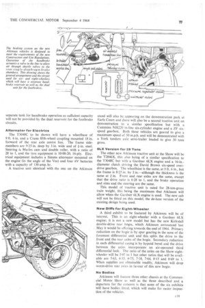
New DIM for Eight-Wheeler
A third exhibit to be featured by Atkinson will be of interest. This is an eight-wheeler with a Gardner 6LX engine; it is not a new model but has the new Kirk stall double-drive rear bogie, which Atkinson announced last May it would be offering towards the end of 1964. Primary reduction on the bogie is by spur gearing in the nose of the foremost differential unit and this splits the drive to the front and the rear axles of the bogie. Secondary reduction In each differential casing is by hypoid bevel and the drive between the axles incorporates an air-operated third differential lock. The ratio of the axles on the Show eightwheeler will be 5-97 to 1 but other ratios that will be available are 5-63, 6-35, 6.75, 7.18, 7-64, 8.15 and 8.69 to 1. When supplies are obtainable readily, Atkinson will drop worm-drive rear axles in favour of this new bogie.
No Bodies Atkinson will feature three other chassis at the Commercial Motor Show as well as the three described and a departure for the concern is that none of the six exhibits will have bodies fitted, which will make for easier inspection of the vehicles.