


New rear-engined passenger chassis from A.E.C.
Page 44
Page 45
Page 49
If you've noticed an error in this article please click here to report it so we can fix it.
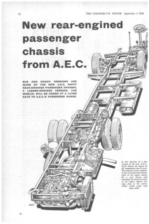
ANEW range of passenaer chassis with rear-mounted underfloor engines driving forward to the rear axle has been announced this week by A:E.C. Ltd. .There. are two basic models which bear the names Swift and Merlin. Full details are known of the Swift only, which is • designed for bodies 36 ft. or 33 ft. long, depending on which of two gearbox options is specified, ' The two models are powered by a new, series of A.E.C. six-cylinder horizontal engines; the Swift by either the AH 471 or AH 505, whilst the Merlin, which it is said will supplement the .Swift at a later date, will have an AH 691. The Merlin will be . designed specifically for overseas markets and full cleats will not be released by A.E.C. for some months: These three engines, from a range which will be described more fully in The Commercial Motor next week, give maximum gross outputs. of 143 b.h.p. at 2,400 r.p.m., 154 b.h.p. at 2,4(X) r.p.m., and 205 b.h.p. at 2,200 r.p.m. respectively, and are essentially dry-liner versions of earlier A.E.C. units, although there are also a number of modifications in other respects.
The Swift is available as a coach chassis with a frame, eat-topped from the rear end to the from axle, or as a bus chassis 'with its frame dropped to a height of 19.5 in. (laden) from in front of the rear axle. On the coach version the frame side-members are 9/32 in. steel channelsection pressings with 3-in -wide flanges and vary in depth from Sin, to 13,7i in., the deepest section being in the area of the rear-spring front hanger brackets. On the bus, the side-members have 3-in. flanges also, but the thickness is *. in. and the depth varies from 8 in. to II:, in., with the maximum being just before the drop down.
Sloped Chassis
Although flat-topped for most of its length, the coach chassis slopes down slightly to the front, the laden height at the rear being 3 ft. 3,1 in. and at the front axle centreline 2 ft. 11., in. The rear end of the bus chassis also slopes down from the rear, being 3 ft. 611{; in. (laden) at this point and 81,in. lower before the members drop to their low level. The side-members rise by 3'4 in. to go over the front axle (after the 19.4-in.-height section), and whilst that on the driver's side stays at the higher level, on the passengerentry side the height is reduced to 167%. in. to allow the
lowest possible entry to be provided in the body fitted.
The wheelbase of both bus and coach chassis is 18 ft. 6 in. and overall width is 8 ft.. In the case of the 33-ft.-long versions, the wheelbase is 16 ft. 6 in. Front and rear overhangs are 7 ft. and 10 ft. 6 in. on the bus and 7 ft. 34 in. and 10 ft. 2 in. on the coach, respectively in each case. The chassis are designed for a maximum gross weight of 12 tons, distributed 4 tons at the front axle and 8 tons at the rear.
The AH 505 engine is standard for the Swift, the AH 471 being optional, and both these engines are based on the previous AH 470 design. Instead of wetliners, dry liners (with obvious alterations to the cylindel-block casting) have been adopted to allow an increase in bore size to be made without the need to change the crankshaft or sump, and with only.relatively minor alterations to heads and block.
In the case of the AH 505, the bore diameter is 4-56 in. (116 mm.) against 4-41 in. (112 mm.) for the AH 470, with the stroke at 5.12 in. (130 mm.), the same as the previous unit. Capacity is 502 cu. in. (8-19 litres). The AH 471 has the same bore and capacity as the earlier AH 470, as well as the same stroke. the designation beim, changed solel}. for identification purposes.
470 Discontinued
With the introduction of the new engines, the AH 410, the smaller-capacity version of the AH 470, is discontinued and, as a result, it has been made possible to increase valve and valve-port sizes they were previously standardized to suit the smaller bore of the 410. This action gives better breathing and volumetric efficiency and has allowed the maximum speed of the engines to be increased by 200 r.p.rn. As stated earlier, at the new speed of 2,400 r.p.m. the AH 505 develops a maximum gross power of 155 b.h.p., against 143 b.h.p. for the AH 471. The maximum gross torques are 3901b.-ft. and 365 ..-ft. at 1.400 r.p.m. respectively. Whilst redesigning the heads and block casting, the opportunity has been taken to increase the number of head studs employed, so that now each cylinder bore is surrounded by six in place of the five studs used on the AH 470. The crankshaft and bearings as used on the AH 470 are continued for the two engines, these being adequate for the speeds and output, as 470s
running at 2,400 r.p.m. have been supplied in the past and turbocharged units of even greater outputs are being suceessfully operated in a number of countries.
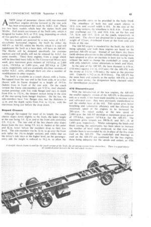
Engine components include a C.A.V. DPA distributortype fuel pump, a 7-in. salternator with an output of 1,440 W., a 5-in, axial starter and a 13.5-cu.-ft. per min, twin-cylinder compressor. In the position that the engine ,s located 1.vith the cylinder heads to the left of the :hassis—all these units are on ton of the engine. Triple pelts drive the alternator and a right-angle gearbox 'mounted on an extension to the crankcase, from which a ;haft extends to drive the fan. This runs in a cowl Ittached to the radiator, which is mounted on the right-land-side side-member, air being drawn from that side of he vehicle. As well as the three belts for the alternator Ind fan drive, the crankshaft pulley has accommodation or a fourth belt, which drives the water pump.
With the radiator located in its particular position, pipevork for the cooling system is straightforward and the :apacity of the system is only 8-5 gal.
On the bus chassis, A.E.C. Monocontrol semi-automatic ransmission is standard, whilst on the coach a six-speed !onstant-mesh gearbox is standard. The latter box is also wadable for bus chassis which are intended for express .ervices. With both transmissions, the unit is directoupled to the engines; with the Monocontrol, a new fluid lywheel designed to suit the characteristics of the AH 505 s fitted and with the constant-mesh box a 151-in.-diameter, iydraulically operated clutch is used. Ratios in the vlonocontrol are 4.28, 2-42, 1.59 and 1 to I with reverse .98 to I, and the design and operation are the same as
vith this transmission used on other A.E.C. vehicles. The onstant-mesh box has an overdrive top gear and has been vailable as an alternative in the Reliance 470 chassis for wo years or so. The ratios are 6-63, 4.44, 2-54, F53, 1 nd 0-75 to 1 with reverse 6.59 to 1. Hydraulic operation or the clutch is provided. The rear axle is a singleeduction spiral bevel with fully floating half-shafts and atlas of 4.08, 4-7, 5-22, 4-87 or 6-28 to 1 are available.
The standard suspension for the Swift is semi-elliptic :af springs at front and rear for both bus and coach ersions. On both chassis the rear springs are 3-5 in. wide nd 62 in. long, and at this point telescopic dampers are tted. For the front axle of the low-frame bus chassis the ront springs are 4 in. wide and 50 in. long, the spring anger brackets being mounted on outriggers from the hassis side-members, and lever-type dampers are fitted to void protrusion above the frame level. In the case of the oach chassis, the front springs are 3.5 in. wide and 56 in. )ng, and their hanger brackets are mounted to the under
side of the chassis side-members and telescopic dampers are used.
Air suspension is available as an option on both types of chassis; at both front and tear' on the coach and at the rear only on the bus. This is Of the same type as used on A.E.C. passenger chassis for some time. The axles are located by parallel (militia radius rods with transverse Panhard rods, and there are two air bellows on each side of each axle. For the front of the bus chassis, a system of combined leaf and air suspension has been adopted, as the low floor height does not allow the use of double-radius arms to give adequate axle location, the main function of the leaf spring being to provide this location.
The braking system is air-pressure operated, with cam brakes at all wheels, these being 15-5 in. by 5 in. at the front for the bus chassis and 15.5 in. by 4.25 in. for the coach chassis, with the rears 15.5 in. by 7 in. for both. The brake units are of Girling manufacture in all cases, except for the fronts of the bus, where they are Leyland. Total frictional area on the bus is 692 sq. in. and on the coach 678 sq. in. The handbrake is air-pressure assisted, the rear-axle brake chambers being Clayton triplediaphragm type. Air pressure is applied behind the diaphragm farthest from the camshaft lever as the handbrake lever, is operated, the valve allowing air into the chamber being located in the rod to the brake levers. The footbrake diaphragm is nearest to the camshaft lever, the third being in between the other two. This is for safety purposes so that puncturing of a diaphragm does not allow a complete escape of air from the system. An advantage of the layout is that whilst the handbrake is applied by air pressure it is mechanically connected to the rear-biake units and is held on in the normal way by a ratchet at the lever. Separate frontand rear-wheel brake circuits are optional equipment.
Standard tyre equipment is radial-steel-cord tyres; 10-00-20, single front and twin rear on the bus, and 9-00-20, single front and twin rear on the coach.
Steering on the bus chassis is Marries cam and double roller with a ratib of 28-5 to 1 or 5-75 turns from lock to lock, whilst on the coach chassis it is A.E.C. worm and nut with a ratio of 40 to 1 or 6-33 turns from lock to lock. Hydraulic power-assisted steering is available as an option, other items of optional equipment including either Clayton Dewandre or Tecalemil automatic lubrication.
The chassis designation of the bus with Monocontrol transmission is M132R, and this model has an estimated kerb weight of 4 tons 10 cwt. For the bus. chassis with constant-mesh gearbox the designation is MP4R, and for the coach CMP4R, the last two having estimated kerb weights of 4 tons 8 cwt.