


SAUFtERS COMBINE MAXIMUM STRENGTH WITH MINIMUM WMGHT.
Page 15
Page 16
If you've noticed an error in this article please click here to report it so we can fix it.
VEHICLES of Saurer manufacture always display remarkable characteristics. They are designed with a view to obtaining the maximum strength -with the minimum weight, and great attention is paid to accessibility and ease of replacements and repair.
The vehicles which will be shown at Olympia are, in some cases, very similar to those shown last -veer. The polished two ton chassis will probably attract most attention. Next will come the five ton three-way hydraulic tipper, which created such interest when it was exhibited for the first time at the last Show. In addition to these vehicles, there will be a 24-seater motor coach and a five ton standard chassis with trailer for Pickford's, Ltd. A two ton rear axle and its gearing will be disassembled in order to show its construction' and particularly the, dog fitting of the bevel wheel and the method of setting the axle at about one and a hall degrees, so that the twin rear wheels accommodate themselves to the road camber.
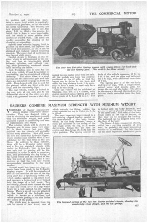
Several small but important improvements have been made to the hydraulic tipping wagon. It, will be remembered that in this machine the ram of the tipping gear has a spherically ended rod, which pushes against a cup-ended lever and operates a twin-armed lever formed into the shape of a bell crank. Two Universally jointed arms connect the end of this bell crank lever to a clap which 'bears on a ball carried by the tipping frame. There is an oil reservoir attached to the barrel of the hydraulic gear, which is known as. a stabilizer, and which prevents jerking of 'the ram under the action of the pump. The whole gear is operated from the cab by means of two levers, one of which controls the lifting, whilst the other controls the way in which the body is tilted.
The most important' improvement is a self-centring cupped bracket carried on the cross-member of the body frame, which, as the body descends, meets a stout pin mounted an the casing of the bell crank lever; the cup, as it moves downwards, brings the pin into its centre, and thus brings the body into the right position. The tipping control rod
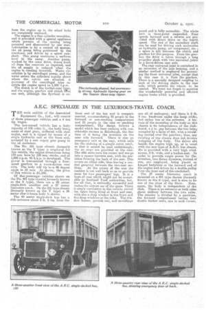
is locked until the body descends, and presses a spring plunger carried on one of the cross-arms. The sides of the body hinge either at the 'top or bottom, so that they can be dropped for loading. The tailboard can be dropped level with the floor of the body. The S.aurer A-type commercial chassis, which has a carrying capacity of five tons, is probably the most, interesting vehicle to be exhibited. In this chassis all the more important mechanical parts
from the engine up to the wheel hubs are completely enclosed. The engine is a four-cylinder monobloc, and is provided with a special appliance which permits of the casting being mounted and dismounted by one man. Lubrication is by a central oil system, the oil pump being pasitioned in the crankcase and driven by a spiral camshaft. This pump maintains a uniform level in the sump. Another pump, worked by the same drive, draws fresh oil from the reservoir as required, and the cail supply is reduced when the engine is running downhill. Water circulation is by centrifugal pump, and the water enters the cylinders exactly above where the valves are situated. A governor of the centrifugal type restricts the engine speed to 1,000 r.p.m. The clutch is of the leather-cone type, and the engine, gearbox and clutch fm one unit, although the flywheel is ex posed and is fully accessible. The whole Unit is three-point suspended. Four speeds forward and a reverse are provided with direct drive on the fourth speed. The end of the secondary shaft can be used for driving such accessories as hydraulic pump, air compressor, etc. ; a space is left between the clutch and gearbox for this purpose. From the gearbox the drive is taken through a long propeller shaft with two universal joints to a bevel-driven rear axle.
The rear universal joint is contained in an extension of the axle housing, and a similar method is employed for protecting the front universal joint, except that in this case it is from the gearbox. There is a specially designed coupling to each of the driving shafts in the rear axle, which permits the wheels to be canted. We must not forget to mention the wonderfully powerful and efficient engine brake which is provided.