


.Self-levelling. Suspension .
Page 86
If you've noticed an error in this article please click here to report it so we can fix it.
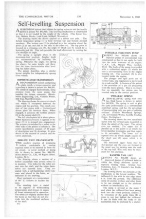
ASUSPENSION system that adjusts the spring action to suit the load is shown in patent No 843,910. The levelling Mechanism is constructed " so that it is not loaded by the weight of the vehicle. (The Rover Co... Ltd., Meteor Works, Lode Lane, Solihull, Warwicks.) The drawing shows the device applied to a driven rear axle. The helical suspension spring (I) is held between top and bottom pivoted members. The bottom one (2) is attached to a bar swinging about the pivot (3) at one end and to the axle at the other (4). The top pivot is located on a swinging arm (5), the angle of which can be varied by a hydraulic. jack (6). This jack provides the load adjustment by rocking the arm through an angle.
The spring is upright when in the 843P10 maximum-load position. Smaller loads are accommodated by inclining the spring. Whatever the angle, the spring has always the same length, and therefore the same characteristics after levelling has taken place.
The patent describes also a similar layout suitable for independently sprung front wheels.
SOPHISTICATED TRANSMISSION A TRANSMISSION system comprising a plate clutch, a torque converter and a gearbox is shown in patent No. 846,091. The clutch is engaged hydraulically, using pressure from the same pump that supplies the torque converter. (Brockhouse Engineering, Ltd., Victoria Works, Hill Top, West Bromwich.)
The drawing shows the converter-clutch unit which is interposed between the engine and the gearbox. The clutch consists of two plates with a friction-faced driven plate (I) between them. When engaged, it connects the turbine element (2) to the output shaft (3).
The left clutch-plate (4) is also a piston. When hydraulic pressure is applied to the space (5) it is pressed into engagement. The pressure is switched by a valve to the other side of the piston to release it. The patent specification consists of 29 pages of description and 26 drawings. It gives details of the method of control and the valves employed.
HOLLOW CAST CRANKSHAFTS THE modern practice of producing hollow crankshafts by casting requires tubes to be inserted to form the oil circuit. A novel method of doing this is shown in patent No, 846,191. (Ford Motor Co., Ltd., 88 Regent Street, London, W.1.) The drawing shows a section of a hollow crankshaft with several tubes (1) in position. The holes for the tubes are cast into the shaft, and the tubes themselves are inserted later. They are coated with a self-hardening epoxy-type resin and placed in the holes, as indicated in the drawing.
Heat treatment at a temperature of 80° C. follows to harden the resin.
The resulting joint is stated to be capable of withstanding temperatures and stresses in excess of those encountered in operation. The tubes are slightly shorter than the bores so that they do not protrude into the machined surfaces of the shaft.
R12
INTEGRAL INJECTION PUMP
PATENT No. 843,046 shows an injection pump of conventional type constructed so that it can easily be built into the main structure of an engine. (C.A.V., Ltd., Warple Way, London, W.3.) The body of the pump is provided with a cylindrical spigot (1) which fits into a corresponding bore in the engine housing (2). The camshaft (3) is also located inside the engine.
The plunger and spill ports are of normal type, and regulation is performed by a rack-rod (4). A feature of the patent is the provision of a pin (5) projecting from the sleeve pinion. This is to ensure that on assembly the pinion can be inserted only in the correct position.
TWO-LEAF SPRING
A SEMI-ELLIPTIC spring with only 2—X two thick leaves is shown in patent No. 845,930. The spring is said to give the same performance as a conventional multi-leaf spring, and has the advantage of incorporating only one pair of rubbing surfaces. (Toledo Woodhead Springs, Ltd., Coronation Works, Aycliffe Trading Estate, Darlington.) The drawing shows the two assembled leaves with the vertical scale magnified to show the detail of the taper. The spring eyes are omitted. The upper leaf is -parallel up to the point (1) at which the lower member terminates, and then tapers to it's extremities. The lower leaf is tapered over its whole length except for the short seat (2) upon which it is clamped.
The tensioned upper faces may be shot-peened and the eyes are formed in the usual way by turning over the ends of the top leaf. 'The ends may be thickened for this purpose.
RAMPED TAIL LIFT
PATENT No. 846,088 shows an improved design of tailboard hoist in which the lifting platform carries a separate sloping ramp. (United Gas Industries, Ltd., 51 Lincoln's Inn Fields, London, W.C.2.)
The drawing shows the elements of the mechanism in the lowest position. The tailboard (1) lies with its rear edge about 6 in. from the ground. The additional ramp (2) enables trolleys and other loads to be run straight on to the platform without an intermediate lift.
The ramp is pivoted at the point 3 and, when the tailboard has been swung back into the raised position, follows it by retraction of the guide links (4) to come to rest just behind the tailboard. It can lie flush with the body or the mechanism may be enclosed by a shutter.