


FORD VAN POINTERS,
Page 25
Page 26
If you've noticed an error in this article please click here to report it so we can fix it.
By R. T. Nicholson (Author of "The Book of the Ford ").
IN my last contribution I opened up on the difficul-' ties attaching to an understanding. of lee electrical cireuits cn the 1920 Ford. I described and illustrated the system as a whole and declared my -intention to reduce its complication to simplicity by splitting the system up into its component parts. We will begin with a very simple bit Of it—the battery—power-starter circuit. I am going to deal with that fi,,, st because it is so simple, and because the tracing of it will be good practice for dealing with more complicated eases later.
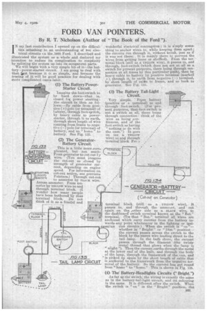
(1) The. Battery PowerStarter Circuit.
Imagine the foot-switch to ' be hard down—that . is, closed bat power starting : the circuit us then as follows:—By cable from positive (-0 pole (or terminal) of 'battery, through foot-witch,
i by heavy cable to powerstarter, through it to earth,
i through short length-of wire running from frame to negative (–) pole (or terminal) of
• battery, and so " home " to battery. See Fig. 133.
(2) The GeneratorBattery Circuit.
This is a. little more ,corn... plicated, but not much: From generator to cut-out Icy wire. (You must imagine the cut-out as closed by strength of generator current, depending on engine speed. Tor information on
r
r (FOOT) Pointers.) Throughcut-out WITCH i to amraeter by rettamic wire.
; .A..cross ammeter. From am
. meter by YELLOW wire to and through terminal block. (I
i wonder how many people have been bothered by that terminal block. Do not think of it as a, fearful and
wonderful electrical contraption; it is simply something to anchor wires to, while keeping them apart ; the circuits run through it, without 'break, just as if it was not there: It is mainly there to prevent the wires from getting loose or shuffled). From the terminal block (still as a YELLOW wire), it passes to, and through, foot-switch (which does not act at all as a switch for .present purposes, there being through connection at all times by this partitular path), then by heavy cable to battery by positive terminal (marked +), through it, to earth from negative (–) terminal, by short length of. calite to frame, and so back to generator. See Fig.. 134.
(3) The Battery Tail-Light ._. Circuit.
Yery simple. . Frprn battery (pesitive or -Iterminal) to and through foot-switch. (For present purposes, that-foot-switch is . not a. switch at all, there being through connection: think of the wire as being con
tinuous, and of the foot-switch as having
"nothing to do with . the, case.") It goes On (as. a YELLOW . wire) to. and through terminal block Fro n
terminal block (still as a YELLOW wire), it
SLACK
passes to, and through the ammeter, and out again on the aother side as a BLACK wire, to the dashboard switch terminal known as the " lat." terminal. (Tot that "Rat.", terminal all wires are anchored which carry current from the battery towards any point whatsoever in the lighting_ or igniA METER tion circuits.) When the switch is " on "— whether in " Bright " or "Dim ". position-the current passes across the switch to the block by the GREEN wire leading direct to the tail lamp. In the bulb there, the current passes through the filament (the twisty metal thread that glows when the lamp is "alight '). Then the current earths through the metal at the lower end \ of the bulb, and through the body of the lamp, through the framework of the van, and TAIL LAMP IRCUIT is anchored to the framework from the negative ter C
FIG /35 is picked up again by the short length of cable that
minal of the battery. So the current has got round
from " home " to "home." This is shown in Fig. 135.
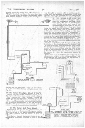
(4) The-Battery-Headlights Circuits ("Bright.")
As far aa the switch; the wiring is exactly the same as in the battery-tail-light circuit, and its colouring is the same. It is different after the switch. When the switch is " on " in the "Bright" position, the;
current crosses the switch from "Bat." terminal to "Bright" terminal, and leaves the latter by a GREY' wire, passing to each headlight, through each bigger bulb filament, and then earths by the metal part of
the bulb and the lamp body, "home" to' the battery, as in the case of the battery-tail-light circuit. See . Fig. 136.
(5) The Battery Headlights Circuit ("Dim ').
Exactly like the bright headlights circuit up to the dashboard switch, then across switch (when in "Dim" position) to "Dim" terminal'; thence by BROWN wire for each headlight. Earthing also is the same. No separate illustration is needed ; but it will be a useful exercise for you to draw one-kr yourself, on exactly the same lines as Fig. 136, but showing the "Dim" connection across switch, and the Foca BROWNwire, and other connections, thereafter. vvrrcH (6) The Battery-Coil-Timer .Circuit.
As you knew, you can use the battery current for ignition—that is, as the Means of firing, your engine. When you so use it, you set the dash.board switch to key "Bat." position, and the circuit is then as follows:— From battery through foot-switch (which is not a / switch a all for present purposes, as there is direct' s52 way through), by YELLOW cable to and through ter. minal block and.ammeter, to dashboard switch (just as in the case of the headlights and tail-light circuit). Then from the "Bat." terminal in dashboard switch: to" Coil " terminal in that switch; then (by BLACK wire) to binding-post behind
dash—the binding-post standing a little lower than the row of sparking-plug cable binding-posts, and towards the right-hand end of that row (Le., the end on your right band when you stand • facing the engine side of the dash). Then through each of the coils in turn, and In turn through each -of the four coloured wires leading to the timer (generally, but wrongly, called the 'commutator ").
There the current, earths throogh the four, metal in
sets in the cover' in turn, and through the roller which rotates as:the eng-ine,runs; and so back to battery • through the earth wire from its-negative Pole. (This low-tension circuit will be more fully dealt with later on when we ..3ome to tracwthe-magneto ignition circuit.) See Fig. 137. My next contribution will, I. hope, conclude this description of the electrical circuits of the 1920 Ford. I have yet to deal with the magneto hoin circuit, the magneto coil-timer circuit, and the high-tension circuit.. I then want to deal with the whole of the ciicuit of the low-tension current, showing its action in the coil, with its make and break mechanism, and the manner in which the high-tension current is produced.
I then Want to"go on and deal just briefly with the colour scheme adopted for the wiring, and then I will try to clear up any little doubts you may possess as to the switches and the ammeter.