


From Engine to Axle.
Page 15
Page 16
If you've noticed an error in this article please click here to report it so we can fix it.
Following the recent papers read before the Institution of Automobile Engineers, which have dealt respectively with rear axles and engines, a third has now been read, dealing with those parts of the transmission which were not included in the previous two reviews. Major Shilson, the author, disclaims any intention to "present any new features or enunciate any new theories," but he has dealt with his subject in an informative manner, and we therefore reproduce 'the paper in instalments as opportunity occurs. The present instalment follows that on page 178 last.
Tooth Form. Gear Ratios.
The author does not wish to commit himself as to the best form of tooth, since this largely depends upon the machines available, and on the experience of the workshop, but probably the commonest form is the 144-degree involute, for which the calculation of the sei-esses is given in the Appendix. The number of teeth should not be less than 15, the shaft centres should not be less than Ali ins, for medium-power touring cars, and 54 ins, for commercial vehicles.
The subsidy specification states that the gearboxes -should be of the four-speed type, and should have reduction ratios of 1, 1.7, 2.9, and 5; the author has found that the best ratio for a total reduction of 4 to 1 is 1, 1.5, 2.5, and 4, and that for a three-speed box a. ratio of 1, 2, 3 is preferable to 1, 2, 4 from the viewpoint of easy gear changing, and that in combination with a suitably-designed single-plate clutch, gear changing becomes almost fool-proof.
To Attain Silence.
A method sometimes adopted to quieten the gearbox on high-class cars when the car is standing and the engine running is to situate the 'constant mesh gears at the back of the box, as shown in Fig. 14, so that with the clutch in, and the ear standing, no gears are running in mesh, and it is surprising that this design has not been more generally adopted. What has probably kept designers from this construction is the fact . that instead of gearing down to the secondary shaft, this shaft runs at a higher speed when on direct drive, and if the reverse gear is always in mesh it results in a very high speed for this piece ; if, however, the reverse wheel is thrown out of mesh, and the laphaft is mounted on ball bearings, the author cannot see any disadvantage in this, whilst the noise from the constant mesh gears in the orthodox position is frequently a decided blemish to an otherwise excellent motor carriage. [Fig. 14 will be found on page 156 ante.] Wide or Narrow Teeth?
It is a debatable point whether a wide or a narrow tooth is the better for a silent-running box. The author's experience is that a narrower gear tends to
greater quietness, but this necessitates a higher quality steel, such as the air-hardening class ; this is not, however, a disadvantage, since this steel, while having a higher first cost, results in a, cheaper box by the time it has left the works if a high-class article is being produced. In fact, in a case which came under the author's notice it was fonnd cheaper to use the same box with air-hardened gears on two different sizes of cars rather than fit case-hardened gears in the one and the more expensive air-hardened gears in the other, as the amount of scrap in hardening and the cost of correcting deformations was much less.
It is hoped that the early practice of running in the gears with emery and oil is now a thing of the past, but that, if it still does exist, the bearings employed for running in are not used in the finished box, and that in*fact a special running-in jig is employed, so that there is no fear of the emery getting into the bearings in service.
A Form of Trouble.
A frequent form of trouble, and one which is sometimes inadvertently attributed to the steel, is that of fatigue of the metal caused by excessive vibration. This shows itself by the teeth tearing out, as shown by the wavy lines in Fig. 15, the fracture being decidedly due to fatigue, and one that is almost sure to occur if the metal in the run at the bottom of the teeth is less than the width of the tooth at its root'; in fact, the metal in a gear should nowhere be less in thickness than at the root of the tooth, otherwise where • the contraction takes place the stress is amplified and trouble will follow sooner or later as the
result of the " " deformation as each successive tooth comes under load in a similar way to the flat on a pneumatic tyre. The trouble is accentuated if the male member of the clutch be too heavy and the clutch stop too fierce, resulting in sudden shocks on the teeth. [-Fig. 15 is not reproduced.] The Change-speed Gear.
The Subsidy Speeification lays, it down, that the change speed gate shall have two slots and two selectors only, and that the reverse slot shall be a continuation of the first speed slot. This is shown in Fig. 16. [Not reproduced.] In Fig. 17 is shown a very satisfactory way of mounting a cross-shaft in spherical bearings which take account of any frame distortion. In this illustration it will also be observed that the change-speed lever is pivoted at the bottom and has a separate arm sliding the cross-tube lengthwise, thus removing any tendency to bind in sliding. The Wolseley Co. were probably the first to use this type of operation on the early Siddeley cars, and it was adopted by many makers before the publication of the' Subsidy Specification. [For fig.' 17 see page 177 ante.]
Where possible it is preferable to mount a changespeed bracket on the gearbox or gearbox arm, and not separately on the frame, on account of frame distortion. In the case of a left-hand drive the gate can be mounted directly on the centre of the box, but English designers hesitate toadopt the centre control as it is not so convenient for operating with the left hand, and from the fear that the levers may be interfered with by a passenger ; experience shows, however, that the operation with the left hand soon loses its strangeness, and that it is then as convenient as in.
the orthodox position, but of course it is quite out of the question to do this on a subsidy lorry according to present legislation.
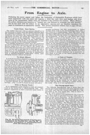
In Fig. 17 will also be seen the locking Cee piece which swings over as the change-speed operating lever slides across, and one or other of the arms of the Cee piece effectively lock the sliding rod or rods which are not intended to move, thus ensuring that only one gear is brought into operation at a time, Another interesting example is that fitted by the Vauxhall Co., in which the sliding rod operates a rotating plate in such a way that only one of the three plungers is uncovered at a time, the others being firmly held down by the plate into grooves formed on the sliding rod. This arrangement is shown on Fig. 18, from which it will be seen that the mechanism performs the dual function of locating one rod lengthwise, and at the same time of locking the others, while the whole is. readily inspected by removing the top cap [Fig. 18 is on the previous page.] Another interesting device for accomplishing the same purpose is shown in Fig. 19, in which two ballended plungers are situated between the rods and separated by a small coil spring. The plungers locate the rods lengthwise by means of countersunk holes in the roA, ;anctiloy correctly proportioning the plunger lengths it is infpossible for more than one rod to move at the same time. This arrangement, which is selfcontained and easily adaptable, obviates the necessity for separate devices for positioning the rod operated and locking the others. [Fig. 19 not reproduced.] Line Adjustment.
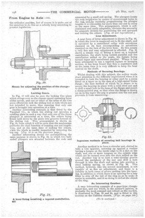
A neat form of lever adjustment is shown in Fig. 20, in which the lever is reamered out to fit the shaft, and is operated by a castellated collar with serrations stamped on its face corresponding to serrations stamped on the face of the lever boss. By this means a very fine and easy adjustment is effected. Fig. 21 shows a simple way of fitting a lever on a tapered castellation, the shaft being turned parallel and the castellation milled on the angle, the female being turned taper and castellated parallel. Where it has been attempted to use a tapered 'square or hexagon section, it has been found that this is expensive and at the same time it is very difficult to keep the boss central on the shaft.
Methods of Securing Bearings.
Whilst dealing with this subject, the author woula draw attention to the difficulty experienced when it is intended to lock the bearing or other part by a piece fitted on a taper as in the case of a, high-Speed brake flange ; the best method of which he is aware is to secure the bearing in place with a mild steel nut and to drill a small hole in the boss of the flange and insert a. sharp-pointed peg, so that when the flange is drawn up on to the taper the peg is pressed into the nut and prevents it from unscrewing.
Another method is to have a circular nut, slotted to take a Cee spanner, screwing up against a washer having a tongue on the inside edge to fit a slot on the shaft, and one or more tongues on the outside edge which can be turned over into the slots milled on the nut. Another way is to turn a semi-circular groove around the periphery of the nut and drill a hole through it into the shaft and spring into position a steel locking spring, as shown in Fig. 22. This method, however, like the second mentioned, is not capable of so fine an adjustment, and there is a liability in both cases of pieces getting into the bearmg, in addition to which there is an opening for a lazy fitter to snip off the tail of the ring so as to make it easier to assemble, and in so doing to defeat the object of the ring.
An Interesting Gearbox.
A very interesting example of a gear-type changespeed box, and one which, in the author's opinion, is probably the most compact and robust on the market, is illustrated in Figs. 23 and 24, and is fitted in this country on the Caledon chassis._ [Figs. on page 156.]