


OPERATION STRIP DOWN
Page 80
Page 81
Page 82
If you've noticed an error in this article please click here to report it so we can fix it.
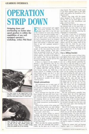
Stripping down and overhauling an Eaton ninespeed gearbox is within the capabilities of any well equipped operator's workshop, writes Phil Reed
Eaton's well-respected and rugged nine-speed gearbox has been widely used both in the (1K and on the Continent for many years. During this time it has earned an enviable reputation for long life and trouble-free service. Yet there comes a time when even the best of gearboxes has to be stripped for overhaul, and carrying this out on an Eaton nine-speeder is within the capabilities of any well equipped operator's workshop.
Over the years there have been several models of the nine-speed box, but only one more major redesign. These later boxes are generally known as -new generation" boxes. The model of box, and its torque capacity, are given in its designation number. The first two figures give the torque capacity, and the last two the number of forward speeds.
If there is a figure 6 in the middle it denotes a "new generation" box. So, for example. a 9509 is the older design or box, the 95 indicating a torque capacity of 1,288Nm (950 lbft), and the 09 the nine forward speeds. An 11609 has a torque capacity of 1,559Nm (1,150 lbft) nine forward speeds, and the 6 in the middle indicates that it is a new generation" box. It is important to quote the designation number in full when ordering spares.
Simple precautions
The illustrations are in some cases of a 9509, and some are of an 11609, but the methods of stripping down and reassembly are very similar with either model of gearbox.
We're assuming here that the oil has been drained, the gear-shift lever housing assembly has been removed and the box is off the vehicle on the bench ready for stripping. Before we start on actual operations, it is as well to take heed of a few simple precautions recommended by Eaton.
Wash off the outside of the casing and clean the bench before you start taking things apart. Dirt is the enemy of any gearbox, and it can knock your bearings out in quite a short time.
Always use proper pullers to remove bearings, and don't leave them lying on the bench. Wash them off, and provided they are in good condition, relubricate them and wrap them up till you're ready to put them back.
When you take the various assemblies apart, such the mainshaft and countershafts, lay the parts out in order on a clean bench. This makes it much easier to put them together again in the right order, and reduces the possibility of losing any parts.
Remove snap rings with the proper pliers designed for the purpose. If you do this, you can use them again. If you lever them out with screwdrivers and grips, you'll ruin them.
Remember that if only the splines or the internal bush on the input shaft, or clutch shaft, are worn, there is no need to strip down the whole box. The shaft can be taken out without removing the mainshaft or countershafts.
We'll have a look first at overhauling the auxiliary sections. Start by locking the box in two gears and take off the output flange nut, after which you can take off the speedometer drive gear and pinion, and lift the output shaft off the back of the box. Undo the cap screws holding the auxiliary sections to the front part of the casing, and look for the three tapped holes in the flange of the auxiliary section.
Use a lifting bracket
If you put three screws in these holes, and tighten them evenly, they will break the joint and move the auxiliary section back about 13mm (1/2 inch) so that you can use a lifting bracket spanning the rear cover to take the weight on a hoist and pull the section back off the dowels.
The next stage is to remove the range shift cylinder. Take off the cover, and the nut on the end of the yoke bar, and then cut the locking wire and take out the screws holding the shift yoke to the bar. Now you can push the yoke bar out the back of the casing, take out the piston and the yoke and take off the cylinder housing. Check the 0-rings on the piston and in the bore of the housing. With this out of the way, you can take the covers off the countershaft bearings, drive the shafts out from the back, and use a soft drift on the outer tracks of the bearings to drive them out towards the back.
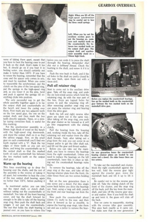
Pull the synchronizer assembly from the output shaft, life off the high-speed synchroniser ring being careful not to lose the three springs, and take the sliding clutch out of the low-speed synchoroniser ring. The output shaft is removed by driving it through from the hack, and the cone of the taper roller bearing will come out with it.
Take off the bearing inner spacer, and use a press to push the shaft out through the gear and bearing, after which you can lift off the splined spacer and stepped washer. The inner and outer tracks of the bearing, and the rear cone, come out after you take off the bearing cover. Check the oil seal in the cover, but unless it has been leaking there is no need to replace it. Driving it out will ruin it.
Putting the output shaft and bearing together again is a straightforward re
verse of taking them apart, except that you have to heat the bearing cone to put it back on the shaft. Don't make it too hot. It should go on if you heat it in boiling water, you should certainly not make it hotter than 135°C. If you have to renew the bearing, remember that the cone and the spacer only comes. in sets, and must be matched. When you come to reassemble the synchroniser, put the clutch on the pins of the low-speed ring, put the springs in the high-speed ring and, as you lower it on the pins, twist and push it against the springs till everything clicks into position.
The only successful way to get the whole assembly together again is to lay the output shaft and countershafts on the bench and lower the casing over them. First mark any two adjacent teeth on the low speed gear, the one on the output shaft, and then mark the two teeth directly opposite. Tipex, or a similar typing correction fluid, is useful for this marking.
Put the synchroniser assembly in a 50mm high block of wood on the bench with the high-speed ring downwards, and stand the output shaft on it so that the splines engage. Now, on the small gear on each countershaft you'll find one tooth marked with a "0". Mark the top edges of these teeth so you can see them, and bring the countershafts up to the output shaft so that the marked tooth on each countershaft lies between the two marked teeth on the output shaft gear.
Warm up the bearing
This lines everything up to drop the housing over the shafts, and the rest of the assembly is the reverse of taking it all apart, but remember to heat the cone of the fear output shaft bearing, again no hotter than 135°C, before pushing it on.
As mentioned earlier, you can take out the input shaft, or clutch shaft, without taking out the countershafts or mainshaft. You take off the front bearing cover, and tap the shaft forward far enough to be able to take off the bearing snap ring, then push the shaft back and wriggle it out past the countershafts. The nut that holds the shaft bearing is peened over, so you have to relieve this
before you can undo it to press the shaft through the bearing. Remember that this nut is lefthand thread. Check the bushing in the shaft, and renew it if it is worn,
Push the new bush in flush, and if the oil holes in the shaft are partly closed by the new bush, open them out with a 4mm drill.
Pull off retainer ring
Next to come out is the auxiliary drive gear. Take off the snap ring, and undo the six lock-wired screws which hold the retaining ring. As with the rear part of the box, there are tapped holes for screws to pull the retaining ring off. After removing another snap ring you can press the retainer ring and bearing from the drive gear.
Both the left and right reverse idler gears are taken out in the same way. After taking off the snap ring, you push the gear cluster as far forward as it will go into engagement with the sliding clutch.
Pull the bearing from the housing and, working inside the box, take off the retaining nut and washer from the idler shaft threads. Next, after taking out a plug from the end, you can screw in an impact puller to get the idler shaft out, and lift out the gear and thrust washer.
Before you can take out the mainshaft, you have to remove the bearings from the right countershaft. Unless you need to replace the bearings on the left countershaft, leave this in place as taking out the countershaft bearings ruins them.
To remove the bearings, take off the snap ring at the rear, and take off the bearing retainer plate from the front. On older boxes there are two screws holding this.
But on the new generation there is one screw and a dowel. Put this single screw back before you drive the bearings out. Next, using a long soft drift, punch the front and rear bearings out from the inside.
Now push the countershaft about 13mm (1/2 inch) to the rear, and then drive it forward as far as possible, to expose the bearing snap rings, take them out and use a puller to remove the bearings.
To take out the mainshaft and cluster, block the right countershaft against the box wall, hold the reverse gear tight against the crawler gear, move the mainshaft back and tilt it up to lift it out.
Be careful not to let the reverse gear slide off. Take the sliding clutch off the front of the cluster, and the snap ring off the back, pull the key from the mainshaft, and take off the reverse gear spacer and washer. Now if you hold the shaft up and twist it, the gears will slide off the back.
Now we come to reassembly, starting with the reverse idler gear assembly. This goes back exactly as it came out, but make sure that on new generation • boxes the collar on the reverse idler gear is towards the bearing bracket. The clearance on the thrust washer is 0.13mm to 0.3mm (0.005 to 0.012 inch).
Countershaft clusters
When it comes to reassembling the countershaft clusters, Eaton strongly recommends that you have in front of you a proper illustrated parts list as this gives all the gear numbers and the order in which they are assembled. On new generation boxes there are marked teeth
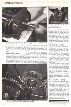
on the countershaft drive gears, but on the older boxes they are stamped with an "0", and it makes timing easier if you mark these teeth on the gear faces as well.
If you've taken out the left countershaft, the one with the larger power take-off gear, this goes back first, followed by the right one. Place them in position, but don't put the bearings in yet.
Before you replace the input shaft, mark any two adjacent gear teeth, and the two teeth directly opposite. Then re place the input shaft from inside the box, and centre the rear end of the countershaft with the special tool. Now mesh the marked tooth on the countershaft drive gear with two of the marked teeth on the input shaft gear. Push in the front bearing, best done with Eaton's special tool, and this will hold the shaft central while you press in the rear bearing and put back the retainer plates and snap rings.
Use illustrated parts list
As with the countershafts, Eaton strongly recommends that you use a proper illustrated parts list to get all the gears, spacers and clutches in the right order, and the right way round, on the mainshaft and to check the axial clearances for the gears. These are adjusted by spacer washers which are colour coded for thickness. The clearances are 0.30mm to 0.90mm (0.012 to 0.035 inch) for the reverse gear and 0.13mm to 0.30mm (0.005 to 0.012 inch) for the forward gears.
Lower the mainshaft cluster into the box, and push it forward to engage the end in the input shaft bush. Replace the right countershaft assembly and mesh the marked tooth with the two marked teeth on the drive gear, making sure that the left countershaft remains in timed mesh.
Then centre the rear of both the mainshaft, using the auxiliary drive gear, and the right countershaft using the special tool.
Remember the snap ring
Push in the bearings on the front of the mainshaft and the two bearings on the countershaft, and lock them up.Take off the auxiliary drive gear, refit the rear bearing, fit the auxiliary drive gear back on the mainshaft and tighten and lock the retainer ring screws. Finally, remember to replace the snap ring, Eaton has a reconditioning centre at Gloucester where it runs training courses on all aspects of maintaining and overhauling its products. It also offers courses at operators' premises where there is sufficient demand.