


A Striking NEW FUEL PUMP
Page 54
Page 55
If you've noticed an error in this article please click here to report it so we can fix it.
for
DIESEL ENGINES
The Benes Device is of Marked Simplicity. It Has No Valves and Operates at a Pressure of 300 Atmospheres
MO work successfully in commercial vehicles, compression," ignition engines must run at comparatively high speeds of revolution, that is, as compared with the rates at which they work in the case of stationary or marine power plant. This involves the use of fuel pumping and metering devices of a distinctly different type from those Which can be used on very large engines operating at low speeds.
• One of the latest products to be placed before the British public is the 13eness pump, designed by Mr. J. Benes, of• Vsetin, Czechoslovakia.
We have inspected a joint report upon the pump, issued by Mr. W. A. Tookey, M.I.Meeh.E.,141.1.A.E., of 39, Victoria Street, London, S.W.1, and Mr. George W. Watson, M.LMech.E., of 50, Pall Mall, London, S.W.1. They tested the device when it was installed on a twocylindered two-stroke-cycle engine; also the pump was dismounted and driven from a lathe for the purpose of further tests. The compression ratio of the engine in question was 19.88 to 1 add the speed range during the trial was 280 r.p.m. to 1,576 r.p.m. Between these limits it proved responsible to control by regulating the quantity of fuel delivered per stroke. The pump is designed to give a discharge pressure of.=.00 atmospheres, or more if required.
During the test, starting of the engine was effected by means of the handle l,lone, no heater plugs or other auxiliary devices being required. It fired immediately after a couple of preliminary turns had been given to ensure the fullness of the pipes leading from the pump to the nozzles.
An Advantage in_Design.
No valves are used in the pump • and no reliance is placed upon lost motion as a means for controlling the quantity of fuel delivered by it. There is also no question of the duration of lift of a relief valve as a means for limiting the fuel output per stroke of the pump.
For the purpose of this description, we treat the pump as intended for a single-cylindered engine. In practice, of course, there is one plunger per cylinder of the engine.
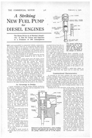
A casing of small overall dimensions has in its lower part a
camshaft driven from the engine; the cam bears upon an adjustable tappet working in a guide, forming part of the lower casing of the pump. The tappet head makes contact with the mushroom-shaped lower extremity of the plunger. This mechanism imparts to it a simple rise-and-fall action. The upper part of the casing consists of an annulat suction chamber ; it also contains the outer cylinder in which are mounted the two working cylinders and the plunger. A reference to the sketches reproduced on this page will indicate the disposition of the components. The working cylindera are two. per plunger ; the upper one is fixed in the outer cylinder, whilst the lower one is movable, and the quantity of fuel delivered per stroke of the pump is controlled by means of its rise or fall.'
Through the plunger is drilled a radial hole, whilst an axial hole runs from the upper end to meet the radial passage.
Constructional Characteristics.
As mounted in the outer cylinder, the upper and lower working cylinders are so spaced as to have an annular passage between them. This is at times in communication with the radial holes in the plunger; at other times the lateral passage in the plunger is sealed by the walls of the lower working cylinder. The annular space between the two cylinders is in communication with the suction chamber, as is the passage surrounding the fixed working cylinder—that is, the upper one of the two.
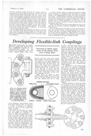
Turning now to the operation of the pump. At the top of the stroke the radial holes in the plunger communicate with the an nular chamber between the working cylinders, and with the suction chamber. As the plunger moves downwards, fuel is drawn in from the suction chamber via the annular spa c e, passing through the radial holes in the plunger and up through the axial passage to the upper part of the working cylinder. Suction continues until the holes in the plunger are covered by the upper edge of the movable cylinder. As the plunger falls yet farther, it uncovers holes in the fixed cylinder, which are in communication with the suction chamber. This allows more fuel to be drawn into the cylinder by the continued downward motion of the plunger.
So far, we have dealt only with
the downward stroke, that is, with the suction stroke. Turning now to the delivery, or upward, stroke, we find that the plunger first covers the radial holes in the fixed cylinder and then forces fuel through a non-return valve to the injection nozzle: Injection
continues until the radial holes fn the plunger begin to communicate with the suction chamber, and the oil in the working cylinder above the plunger takes the easiest course to the suction chamber so that the remaining portion of the stroke of the plunger is ineffective, so far as injection is concerned. It will be realized that the position of the movable cylinder relative to the fixed cylinder controls the effective length of stroke of the pump, therefore limiting the quantity of fuel delivered to the engine Cylinder. The total stroke of thellenes pump plunger is, roughly, 50 per cent. greater than the maximum effective stroke required. No provision is made for varying the timing of injection. A non-return valve is fitted in the fuel nozzle.
We are informed that the pump has operated on an engine of the two-stroke-cycle pattern running at 1,800 r.p.m., the power unit in question developing 26 1.h.p. at 1,200 r.p.m., whilst it has operated at a speed so low as 100 r.p.m. without misfiring. A sample plunger which we inspected measured roughly 3+ ins. in length. A coniplete pump would have an overall height in the neighbotirhood of 8 ins. and could be installed very easily. No side thrust is taken by the pump plunger as the cam acts, in the first case, upon the tappet and the lift, as transferred to the plunger, is purely a vertical one. The oil pressure also is evenly distributed over the head of the plunger, and there is nothing to cause a tilting action with consequent rapid wear.
Those interested in the Benes pump should get into touch with Mr. C. Peterka, Buchanan Buildings, 24, Holborn. London, E.0.1.
It is very important to note that in a more recent development the inventor obtains uninterrupted suction without a vacuum, and thus' he ensures entire freedom from vapour, etc., in the delivery connections. This feature is not shown in the sketches reproduced on the previous page, as details were not available at the time of going to press.