


ANOTHER SELF-TRACKING SIX-WHEELER.
Page 30
If you've noticed an error in this article please click here to report it so we can fix it.
A Resume of Recently Published Patent Specifications.
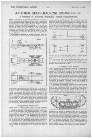
THE self-tracking six-wheeler described in specification No. 299,506 by Cecil Hubert Hylton, bears a resemblance to two previous patented inventions which have rebeeiatly been described in this journal. The patents to which we refer are
281,908 Whitby, and 294,333 Reynolds. It is not our business to inquire into the methods of the Patent Office, reforms of which are at the moment being suggested by competent authorities, but, apparently, some of these patentees may find that they will not get much in the way of a monopoly in return for the fees they have paid to the Patent Office. • In the present invention, as in those mentiomed above, the act of Writing, by means of the steering wheels, diverts the
frame from a straight line, as in Fig. 2, and in doing so the uslee of the bogie automatically take up the position shown in Fig. 3. This is accomplished by Means of the springs, which act as torque and radius rods, being provided with pivots with vertical axes where they are attached to the frame, and with similar pivots where they join their axles. We haVo added dot and dash Mee to the drawing indicating the directions of the various axles when cornering, from which it will be seen that all the lines approximately meet at one common centre, around which the vehicle is turning. Axles without torque tubes are shown, the springs being of the double type, which take the torque reaction.
Compensated Brake Rods.
TEIE name of Ettore -Bugatti, which has been connected
with many useful inventions in motor construction, appears in patent No. 279,116. The invention described is for a new method of compensating the pull-on brake rods. As shown, it is applied to four-wheel • brakes, but there is no reason why it should not be applied to all kinds of brakes that act
directly on the wheels. The. compensation of brakes is looked upon by some as a dangerous practice, as, in ordinary circumstances, should One-rod break or be thrown out of action, not only would one brake become inoperative, but the brake on the opposite wheel would be useless also.
In the present •case, the inventor realizes this and has provided a means for compensation which, should one rod fail, would enable the remaining rod to function, not quite as B46
usual, but to a useful extent. .The. specification drawing shows the brake pull rods in the fOrm of cables,. which run from rear brakes over pulleys attached to levers on 21. 'rocking shaft to •the front brakes. So far, there. is nothing ne-W in the design as the compensation between front and renr-. brakes in ;his manner is known. It will be seen, however, that the tables, in One place, are drawn slightly out of their
straight line by a cross rod which carries a pulley at each end and is free to slide endwise, but cannot move fore or aft.
It will be seen that by this means both cables must bear the same tension when the brakes are applied, hut, should one go out of action, the remaining one would assume a straight line and continue to act.
An Endless Track Vehicle.
TEE double chained arrangement described in specification No. 299,609, The Linn Manufacturing Co., of New -York, appears to have a novel feature in the arrangement of the rollers which act between the chain that lies on the ground and the means of support attached to the frame. In most of the endless track arrangements the entire weight of the frame and its load is carried on rollers which revolve around pins or axles.In such arrangements a very heavy load has to be borne on a comparatively small surface, and constant lubrication is necessary. As such rollers have to work in conditions where grit is very likely to be Present, the life of such bearing surfaces is usually short.
In the present arrangement the outer chain, Which comes in contact with the ground, has an inner surface which is more or lees continuous, whilst two members which bear a resemblance to violin cases are hinged at their centre to a rocking member which is again hinged to tbe main frame. Between the lower fame of these members and the inner face of the outer chain, the weight-supporting rollers roll, not
supporting the weight by means of their pins or axles, but by a true rolling action as in a roller bearing. These rollers are connected together by means of links, thus forming a chain, but not a driving chain, as it merely idles round, the outer chain being the. means for driving by way of the sprocket shown on the right, which is the rearmost, and is driven by means of a rack ring and pinion from a differential. The arrangement appears to be a distinct advance on . the usual plan, as all load is relieved from between the rollers and the pins on which they run, consequently lubrication is hardly necessary and friction is greatly reduced.