


THE SHIPPING OF LARGE VEHICLES.
Page 19
Page 20
If you've noticed an error in this article please click here to report it so we can fix it.
Some Details of the Special Apparatus Used by a Railway Company to Facilitate the Work of Shipping Heavy Vehicles from Heysham to Belfast.
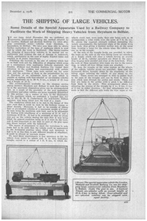
IN our issue dated November 6th we published an interesting illustration showing the method adopted by the London, Midland and Scottish Railway Co, when shipping commercial motor vehicles from Heysham, in Lancashire', to Belfast We have now been able to obtain further particulars of the type of appliance which is used and by which the work is facilitated. .Tho device, enables the shipping of heavy-duty vehicles to be carried out expeditiously and without the risk of damage to bodywork, which, particularly in the case of highly finished buses and coaches, is of prime importance.
Following the increase in the size of vehicles which had to be dealt with and the difficulties of shipping which arose as a consequence with appliances hitherto employed, the London, Midland and Scottish Railway Co. turned their attention to the problem and experimented with certain new appliances. These tests were carried out for some time and the outcome of them is the introduction for use at Heysham of an adjustable form of gear which is capable of dealing with four-wheeled or six-wheeled vehicles having wheelbases up to 20 ft. 6 ins., a weight of 10 tons and a height of 10 ft.
The accommodation available on the . steamer service plying between Heysham and Belfast is such that vehicles up to the maximum dimensions given can be accommodated and, as a result of the provision of the new appliances, motorbuses and other vehicles are being regularly despatched by this service. As a matter of fact, in the illustration of the appliance which we published, a Leyland bus, for use by Mr. H. M. S. Catherwood, the well-known Belfast operator, was being lifted into the hold of a vessel.
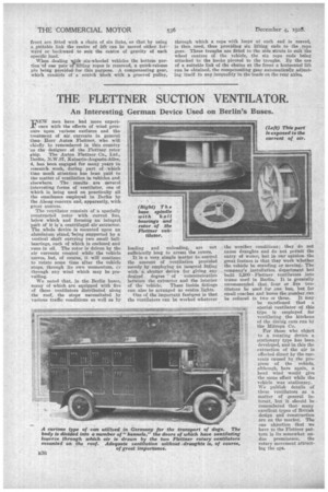
The conditions which had to be met in the design of this gear were that it could be used by the harbour cranes or ships' derrick. Moreover, it had to be capable of lifting four or six-wheeled vehicles of a maximum weight of 9 tons, 43. tons being the maximum axle load, and to be adjustable for dealing with wheelbases of a minimum of 11 ft. and a maximum of 20 ft. It had to be arranged so that no stress was put on the vehicle during the time that it was being lifted, its general condition being as if it were on the 'road, and it was important to see that no part of the gear came into direct contact with the bodywork. The means of adjustment to meet the variations in axle loads had to be such that the vehicle could be maintained in the horizontal position when lifted and, moreover, it had to be so fine that, to suit different lengths of wheelbase, it could be altered in one-inch stages. To meet these requirements it was necessary to lift the vehicle from under its wheels and, to do this, steel-plate troughs, curved to a radius of 1 ft. 6 ins., in which the
wheels could rest, were made, their size being such as to
adcommodate a total width over the tyres of 7 ft. ins. To obtain the required strength without increasing the weight unnecessarily, the upturned edges of the plates were bent back, thus giving a buckled section and, at the some time, forming a ramp for the wheels when the vehicle was run on to the troughs.
At the ends of the troughs hooks are provided, to which the loops on the ends of the wire lifting ropes are attached. At a height which will clear a vehicle having an overall height of 10 ft., tubular spreaders are fitted to the ropes, 'thus keeping them parallel and clear of the bodywork. From the ends of these spreaders wire ropes are run to the centre ring, to which all-four lifting ropes are attached.
To keep the troughs at the same centres as the wheels pf the vehicle, tubular struts are provided; these take the horizontal thrust brought 'alreut by the 'angularity of the lifting ropes relieving the vehicle of any stress on the wheels. These struts are arranged to slide in guides fixed to the ends of the troughs and can be fixed to them by pins which pass through the guides and struts. There are four pin holes in the guides with a pitch 1 in. different from those in the struts. .This arrangement allows for adjusting the centres of the troughs by 1 in., 2 ins., 3 ins. or 4 big, in either direction. So that adjustments can be made to guit the different axle loads the wire ropes at the
front are fitted with a chain of six links, so that by using a etiltable link the centre of lift can be moved either forward or backward to suit the centre of gravity of each specific load.
When -dealing math six-wheeled vehicles the bottom pertion`of one pair oflifting ropes is removed, a quick-release pin being Provided for this purpose. A compensating gear, consistsof a snatch block with a grooved pulley,
through which a rope with loops at each end is reeved, is then used, thus providing six lifting ends to the rope gear. Three troughs are fitted to the side struts to suit the wheel centres of the vehicle, the six rope ends being attached to the hooks pivoted to the troughs. By the use of a suitable link of the chains at the front a horizontal lift can be obtained, the compensating gear automatically adjusting itself to any inequality in the loads on the rear axles,