


THE LEYLAND CROS 4TRY SIX-WHEELER.
Page 16
Page 17
Page 18
If you've noticed an error in this article please click here to report it so we can fix it.
A Highly Efficient Goods-tra: Service at Home or in licle Designed for Arduous Developed Countries.
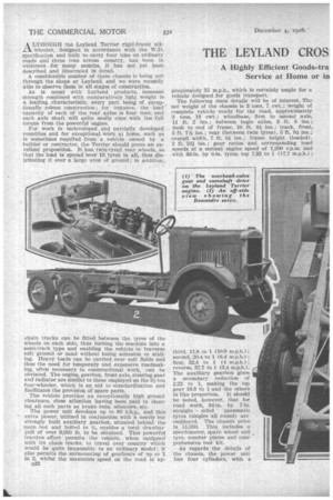
A LTHOLTGH the Leyland Terrier rigid-frame sik...AL wheeler, designed in accordance with the W.D. specification and built to carry four tons on ordinary roads and three tons across country, has been in existence for many months, it has not yet been described and illustrated in detail.
A considerable number of these chassis is being put through the shops at Leyland, and we were recently able to observe them in all stages of construction.
As is usual with Leyland products, immense strength combined with comparatively light weight Is a leading characteristie, every part being of exceptionally robust construction ; for instance, the load capacity of each of the rear axles is four tons, and each axle shaft . will quite easily cope with the full torque from the powerful engine.
For work in undeveloped and partially developed countries and for exceptional-work at home, such as Is sometimes requii7ed from a vehicle owned by a builder or contractor, the Terrier should prove an excellent proposition. It has twin-tyred rear wheels, so that the load Is spread over 10. tyres in all, thus distributing it over a large area of ground ; in addition, chain tracks can be fitted between the tyres of the wheels, on each side, thus turning the machine into a semi-track type and enabling the vehicle to traverse soft 'ground or sand without losing adhesion or stalling. Heavy loads can be carried. over soft fields and thus the need for temporary And expensive roadmaking, often necessary in constructional work, can he obviated. The engine, gearbox, frcint axle, steering gear and radiator are similar to those employed on the 3-tort four-wheeler, which, is an aid to standardization and facilitates the provision of spare parts.
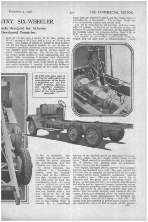
The vehicle provides an exceptionally high ground clearance, close attention having been paid to clearing all such parts as brake rods, silencers, etc.
The power unit develops up to SO b.h.p., and this extra power, utilized in conjunction with a neatly but strongly built auxiliary gearbox, situated behind the main box and bolted to it, enables a total drawbar pull of over 9,000 lb. to be obtained. This poWerfuI tractive effort permits the vehicle, when equipped with its chain tracks, to travel over country which would be quite impassable to an ordinary model; it also permits the surmounting of gradients of up to 1 in 2, whilst the maximum speed on the road is ap n32 proximately 35 m.p.h., which is certainly ample for a vehicle designed for goods transport. •
The following main details will be of interest. The net weight of the chassis is 3 tons, 7 cwt.; weight of complete . vehicle ready for the road, approximately 3 tons, 18 cwt.; wheelbase, first to second axle, 11 ft. 2 ins.; between bogie sides, 3 ft. 8 ins.; dash to end of frame, 16 ft. 61 ins.-' track, front, 5 ft. 7/1T ins.; rear (between twin tyres), 5 ft. 9/ ins.; .overall width, 7 ft. Oi. ins.; frame height (loaded), 2 ft. 101 ins.; gear ratios and corresponding road speeds at a normal engine speed of 1,200 r.p.m.• and
with 36-in. by 0-in. tyres, top 7.33 to 1 (17.7 ;
third, 11.8 to 1 (10.9 m.p.h.); second, 20.4 to 1 (6.4 m.p.h.} ; first, 32.4 to 1 (4 m.p.h.) ; reverse, 37.7 to 1 (3.4 m.p.h.). The auxiliary gearbox gives a secondary reduction of 2.22 to 1, making the top gear 16.3 to 1 and the others in like proportion. It should be noted, however, that for road work, 34-in, by 7-in.
straight sided pneumatic tyres (singles all round) are employed. The chassis price is £1,050. This includes a speedometer, spare wheel and tyre, number plates and comprehensive: tool kit.
As regards the details ,of the chassis, the power unit has four cylinders, with a bore, of 4T9-e ins, and a stroke of 51 ins., giving an R.A.C. rating of -33.3 h.p., and a b.h.p. of 50 at 1,000 r.p.m. The engine is similar in design to that utilized on all the latest Leyland models, in that it has an overhead camshaft driven by chain and helical gears, the smaller gear being in halves sprung apart by small compression springs. The valves are operated by rocker arms capable of easy adjustment, and the whole valve mechanism is enclosed and thoroughly lubricated, the camshaft running in a trough and splashing oil on to the cover, from which it drips into the rocker bearings. A massive, dynamically balanced crankshaft of angle steel runs in five main bearings
21 ins, in diameter. The cylinder head is quickly detachable for valve grinding and decarbonizing and .the cylinders are cast en bloc.
To avoid vibration, the crankcase is thoroughly webbed, also the holdingdown bolts of the cylinders pass right through the crankcase and serve to hold the main-bearing caps. A timing chain is utilized to drive the fan, a small friction clutch being interposed; this obviates any trouble with a fan belt, which is one of the most frequent causes of vehicle stoppage. Circulation of the cooling water is effected by a centrifugal pump with an accessible gland, and the temperature is controlled by a thermostat. The radiator itself has a cast-aluminium header and bottom tank.
The oil is force-fed to all bearings and the sump holds 2/ gallons. A feature of the system is that the pressure is automatically controlled by the position of the throttle pedal, the pressure falling from 5 lb. to 80 lb. per sq. in., according to the requirements.
The system of carburation is extremely well arranged and the inlet pipe is exhaust-heated. Snap opening of the throttle gives an immediate response, and the engine can give steady pulling down to 200 r.p.m. Hand control is provided for the h.t. magneto, but, if desired, coil ignition with an automaticadvance device can be supplied.
-The engine, dry-plate clutch, gearbox and auxiliary gearbox are mounted as a unit. The gear control for the main box is mounted on the off-side cover, whilst a smaller lever, more centrally positioned, controls the auxiliary gear. The gear ghafts are 21 ins, in diameter and the gears have a maximum width of ins. A speedometer drive is provided, and all gears and shafts can be removed through inspection covers.
A one-piece propeller shaft of tubular construction takes the drive to the bogie forward axle and a similar, but, naturally, shorter, shaft connects the two worms, which are mounted above the worm wheels.
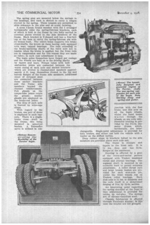
Unlike most bogie arrangements, the Leyland embodies a single inverted leaf spring at each side. The spring ends are enclosed in grease boxes, leather muffs preventing the entry of dirt or egress of the grease. The spring pins are mounted below the springs in the housings, and each is slotted to carry a tongue riveted to the spring. These tongues are permitted to slide sideways in the pins and so avoid twisting.
A stout I-beam forged member with the I arranged horizontally' joins the spring-fulcrum brackets, each of which is held to the frame by two bolts carried in external plates riveted to the side members of the frame. Each bracket is Y-shaped and has a four-bolt. cap at the base to carry the spring-fulcrum pin with its bronze bush. The centre beam supports two brake cross-shafts, the levers on these having rods equipped with neat, capped bearings. The rods extending to the brake-operating shafts of the third axle are in tension when the brake is applied, but the front rods are in compression and for this reason they are made as tubes; in each case adjustment is easy.
The bogie axles themselves have forged pot casings and the wheels are held on to the driving shafts by tapers and keys. Torque tubes with balland-socket joints are connected between the worm casing of each axle and anchor brackets which are riveted to channel-steel members approximately 4 ft. long, themselves riveted to the top and bottom flanges of the frame side members. Additional stays of stripped steel are connected between these anchor brackets and the frame side members beyond the channel reinforcement. Felt glands on the torque-tube joints retain the grease; similar glands are employed on the brake-rod joints.
The drop of each axle is limited by wire-rope With regard to the brakes, one pair of shoes is employed in each rear axle. There is a singlebrake cross shaft on the frame, this being mounted in spherical bushes. A Dewandre servo is utilized in con junction with the foot brake, and this acts on all the bogie wheels, whilst the hand brake works through the wheels on one axle only. Powerful braking is provided by the 17i-in. diameter drums, which, incidentally, are interchangeable. Single-point adjustment is provided for both brakes, and either can hold the vehicle with a. trailer on the stiffest incline.
Deep rubber stops in brackets bolted to the side members are provided above each axle end. The frame is straight and tapers to the front only. It is 7i ins, deep and has 3i-in. flanges at the maximum.
Steering is effected by a gear of the worm-and-sector pattern equipped with Timken combined thrust and journal bearings. The segment shaft is mounted in an eccentric bush to permit accurate adjustment. A roller thrust race and large bronze bushes are provided for each stub-axle pin, whilst the front wheels run on Timken: roller bearings. Each stub. axle is 2i ins, in diameter and the axle • itself i a nick-el-steel • forging of 3-in. by 2i-in. section.
An interesting point regarding the spring shackles at the front is that adjustment is provided for • taking up end-play. The springs are of chrome-vanadium steel.
Chassis lubrication is effected through .Tecateritit nipples; in this caSe the nipples are not grouped.