


AN ASSISTANT TO THE BRAKE PEDAL.
Page 14
Page 15
If you've noticed an error in this article please click here to report it so we can fix it.
A Technical Description of a Device Which Puzzled Visitors to the Motor Show, but is Really Very Simple.
\XTE have already given a brief V description of the brake introduced by Safety Servo Brakes, Ltd., of 418, Cecil Chambers, Strand, London, W.C.1, but at the time of the appearance. of our previous article we had very little detail information with which to describe this somewhat curious mechanism: The title "Servo," meaning slave, is' not a happy choice, as it implies that some outside power does the work as in the case of most of the servo brakes, Whereas, in the present arrangement, there is no assistance from any -outside 'source, the whole of the potver used for the application Of the brake coming from the driver himself, in the form
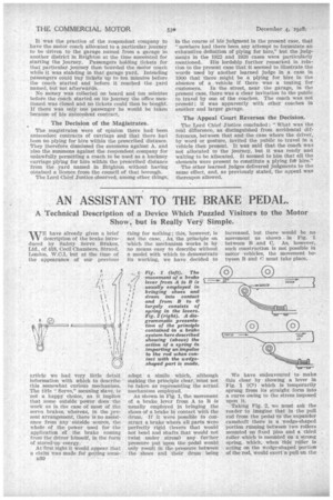
of stored-up 'energy.' . • At'first sight it would appear that a clairn was inaCie for getting some n30' thing for nothing ;•this, 'however, is not the case: As the principle on 'which the mechanism works is by no means easy to describe without a model with which to demonstrate its working, we have decided to adopt a simile which, although Making the principle clear, 'must not be taken as representing the actual mechanism eniployed. • • As shown in Pig. 1, the movement of a brake lever from A to B is usually employed in bringing the shoes of a brake in contact withthe drum. If it were Possible to Con.struct a brake where all parts were perfectly rigid (levers that would not bend and shafts that would not twist under stress) any further pressure put impi the' pedal would. only result in the pressure between the shoes • and their drum • being increased, but there would be no movement as shown in Fig. 1 between B' and C. As, however, such construction is not possible in motor -vehicles, the movement between B and C must take place.
We have endeavoured to make this clear by showing a lever in Fig. 1 (C1) which is 'temporarily sprung from its straight form into a curve owing to the stress imposed upon it. Taking Fig. 2, we must ask the reader to imagine that in the pull red from the pedal -to' the-eXpander .camshaft there is a wedge-shaped portion running between two rollers mounted on fixed pins and a third roller which is mounted on a strong spring,. which; When thiS roller Is acting on the wedge-shaped portion of the rod, Would exert a' pull on the
rod of, say, 200 lb. We will now Imagine that a pull of 100 lb. is exerted by the driver on the rod, as is shown in both views in Fig. 2 at the right. So long as the lower roller presses on the parallel part of the rod, the pull of 100 lb. would not receive any assistance from the stored-up energy in the spring, but, when
t h e springmounted roller comes in contact with the wedgeshaped part, it imparts to the rod a pull of 200 lb., thus resulting in a total pull of 300 lb. on the rear portion of the rod. This may be taken roughly as an explanation of the working of the device. But it might be asked : " If the stored energy in the spring can help in applying a brake, the spring must be re-charged ; where, therefore, does the power come from to recharge the spring?"
The answer to this is simple, as it is the returning of the levers that have b'een temporarily distorted (as shown on the left in Fig. 1) and the untwisting* of the shafts, etc., that supplies the power to re-charge the spring.
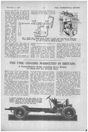
In the actual device, a cam with a concentric part and a sloping part takes the place of the sliding bar which we have used in the demonstration diagrams in Fig. 2, a roller being pressed against the cam by means of a lever and a strong spring. The whole device is contained in a compact box (shown
partly opened up in Fig. 4) which can be filled -up with oil. A selfadjusting device by means of a ratchet and pawl is employed so that when the movement •necessary to apply the brake exceeds a predetermined amount, a tooth is taken up • by the ratchet, thus having the effect of shortening the rod and so adjusting the brake automatically as required.