


A Novel Mounting for Steering Wheels
Page 74
If you've noticed an error in this article please click here to report it so we can fix it.
THE method of mounting steering wheels, which is shown in patent No. 351,379, by Achille Arato, 47 eorso Pratte* Turin, is particularly sound from a mechanical Point of view, as it affords a perfect support for the stub axle without putting any overhanging stress on any part.
The wheel is of the single-disc type, and has the axle secured to it by means of a flange which can be of ample dimensions. The bearings are mounted in a member which forms a double support for the steering pivot pins, each of these being in double-shearing stress.
The steering pins can be made working fits in either the fork ends or in the steering member.
By use of this arrangement the wheel can, if needed, be brought directly central with the steering pivot and both the bearings can take an even share of the load.
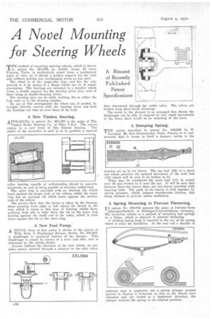
A New Timken Bearing.
APPEARING in patent No. 351,370 is the name of The Timken Roller Bearing Co., of Ohio, U.S.A. The patent relates to a new form of this famous bearing. The object of the invention is said to be to product a tapered roller bearing capable of withstanding thrust in opposite directions, as well as being capable of carrying radial load.
The outer ring is provided with an internal rib, which bears against the larger ends of the rollers, whilst the inner ring has an external rib which bears against the smaller ends of the rollers.
The arrows show bow the thrust is taken by the bearing, those pointing from right to left taking the thrust in the way which is usual to this type of bearing, whilst those pointing from left to right show the rib on the inner ring bearing against the small end of the roller, which in turn bears against the rib on the outer ring.
A New Fuel Pump.
A NOVEL form of fuel pump is shown in the patent of
Willy Seek, 3, Duisburger Strasse, Berlin, No. 351,604. A diaphragm is employed instead of the plunger. This diaphragm is raised by means of a lever and cam, and is depressed by the spring shown.
Arrows indicate the direction of the fuel, which, we presume, passes upward through a strainer to the inlet valve, then downward through the outlet valve. The valves are formed from sheet-metal pressings..
The notch in the plunger is so arranged that should the diaphragm not be able to respond to very :rapid movements of the lever, there would be no straining of the lever.
A Damping Spring.
THE spring described in patent No. 349,926 by E. Burnand, 49, Rue Desrenaudes, Paris, France, is so constructed that• it farms in itself a damper, owing to the
friction set up by its leaves. The tap leaf (22) is a short one which prevents the upward movement of the next leaf (16) which will be seen to be broken at 21.
What may be considered the main leaf (17) is curled over 16 and riveted to it near the eye. It will be seen that between these two leaves there are two leaves provided with tapering ends. The pack of six leaves is held together by spring pressure, which induces considerable friction, this being claimed to prevent undue oscillation.
A Spring Mounting to Prevent Fluttering.
IN patent No. 350,884 appears the name of Daimler-Bens Aktiengesellschaft, of Stuttgart-Untertiirkheim, Germany. The invention relates to a method of mounting leaf sprints on a frame, which is claimed to prevent fluttering.
A yielding spring bush is inserted in the eye of the spring where it joins the dumbiron. At the rear end a shackle of