


Patents Completed.
Page 26
If you've noticed an error in this article please click here to report it so we can fix it.
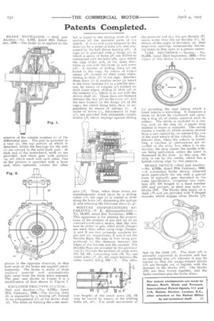
BRAKE MECHANISM. — Hall and Another.—No. 4,868, dated 28th February, 1906.—The brake (1) is applied to the
exterior of the outside member (r) of the differential gear. The gear is mounted in a case (a), the top portion of which is detached, whilst the bearings for the axle (j) are carried in the solid body part. At each end of the brake-band, teeth (a) are provided, and these gear with pinions (m, ml) which mesh with each other. One of the pinions is provided with a lever and, when operated, rotates the other
pinion in the opposite direction, so that both ends of the brake are applied simultaneously. The brake is made of stout resilient material and automatically falls away from the drum when released. The gear case shown in Figure 2 is a modification of that shown in Figure 1.
ENCLOSED DISC-TYPE CLUTCH.— Hall and Another.—No. 4,783a, dated 27th February, 1906.—The driving shaft (b) is supported by a bearing (dl) formed in an enlargement (C) of the driven shaft (d). The drum (a) forming the outer mem ber is keyed to the driving shaft 01 and encloses all the movable parts of the clutch, al is an end cover fastened to the drum (a) by a series of bolts (a3), and supported by the ball thrust bearing (a2). A cage (e) is provided with a flange (e1-) in which a series of holes (e) are drilled to correspond with the bolts (a3), upon which the cage slides and, at the same time, turns as one with the drum (a) and cover (al). A number of sliding discs (f) are keyed to the cage, by means of tongue pieces (p) formed on their outer edges, sliding in slots (f2) in the cage. Between these discs (f) is another series (g) keyed to the inner member (C) in a similar manner, by means of tongues (e) formed on their inner edges, sliding in slots (g2) in the member (C), which is in one with the driven shaft (di. These discs are clamped between the face (ai) on the cover fa') and the face formed on the flange (e4) of the cage; the clutch being held, thus, in engagement by means of springs (if. A series of levers (j), fulcrummed in lugs (A, are provided with adjustable contact screws (14) which impinge against sliding p as (j5). Thus, when these levers are s•multaneously acted upon by a sliding collar (/2), the cage (e) is caused to slide along the bolts (a3), depressing the springs (i) and releasing the frictional discs (I, g).
MIXTURE PROPORTIONING AI'. PARATUS.—F. K. Aktiengesellschaft.— No. 24,507, dated 2nd November, 1906.— This apparatus is for altering the proportions of the mixture of gas and air in an internal-combustien motor, that the mixture be richer in gas, when small charges are used, than when using large charges. A and B are two prismatic conduits for gas and air, respectively, F and G are the throttle flaps, the area of flow being proportional to the distance between the edges of the throttle and the conduit. The throttle flaps are actuated by the governor rod (L) through the medium of crank arms (kl, k2, k3), connecting rods (141, N), and crank arms (j1, AA), the angle between the latter cranks being 180 —O. The effec tive lengths of the crank arms (k2, k3i may be varied by means of the shifting bolts (nl, m1). For small movements of
the governor rod (L), the gas throttle (F) opens wider than the air throttle (G), by reason of the angle of deviation (a), their respective openings subsequently becoming equal as they open to a greater extent.
TIME RECORDER. — Hering. —No. 21,096, dated 22nd September, 1906.—The object of this device is to provide means
for recording the time during which a hired vehicle is travelling. It comprises a drum (a) driven by clockwork and carrying a ring (d) of elastic material such as rubber. The whole is enclosed in a casing, and, on the ring (d), a paper strip marked in hours is mounted. The casing carries a needle (1) which receives motion from a cam carried by, or operated by, one of the road wheels of the vehicle. It thus follows that, when the vehicle is travelling, a number of perforations are recorded on the strip, but, when it is stationary, the strip passes the needle without being perforated, unless the latter is depressed at the time, In this case, the strip is cut by the needle, which has a lateral cutting edge for this purpose.
BRAKE DEVICE.—Hall and Another. —No. 4,783s, dated 27th February, 1906. —A convenient brake device, intended more particularly for use with a special form of epicyclic gear described in the same specification, comprises two members (1)2, 1)4) hinged to a fixed member (D3) and pivoted, at their free ends, to blocks (D5). The blocks slide freely on a shaft (13) and are provided with V-shaped recesses which engage other blocks (f1) fast on the shaft (f2). The shaft (f2) is pivotally supported in brackets and has an operating arm (f4) whereby it may be turned so that the wedge-shaped blocks (J'I) are brought out of register with the recesses in the blocks (D5). The blocks iDl) are thus forced together, and the brake members grip the brake drum.