


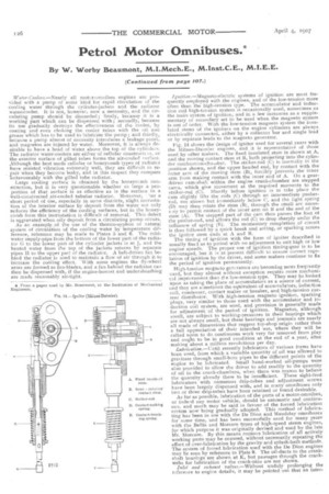
Petrol Motor Omnibuses.*
Page 20
Page 21
Page 22
Page 23
Page 24
Page 25
If you've noticed an error in this article please click here to report it so we can fix it.
By W. Worby Beaumont, M.I.Mech.E., M.Inst.C.E., M.I.E.E.
(Contiwied from page 107.)
Water.Coolers.—Nearly all motcr-omnibus engines are provided with a pump of some kind for rapid circulation of the cooling water through the cylinder-jackets and the radiator water.cooler. It is not, however, now a necessity, and the circulating pump should be discarded ; firstly, because it is a working part which can be dispensed with; secondly, because its use gradually destroys the effectiveness of the cooler, by coating and even choking the cooler tubes with the oil and grease which has to be used to lubricate the pump ; and thirdly, because a pump almost of necessity introduces a leakage point, and magnetos are injured by water. Moreover, it is always desirable to have a head of water above the top of the cylindefs. The radiator water-coolers are either of cellular constructim, or the exterior surface of gilled tubes forms the air-cooled ,urface. Although the best made cellular or honeycomb types of radiatcr have resisted vibration extremely well, they are difficult to re. pair when they become leaky, and in this respect they compare unfavourably with the gilled tube radiator. Large cooling surface is obtained by the honevccmb construction, but it is very questionable whether so large a proportion of that surface is as effective as is the surface in a well-constructed air-cooled tubular radiator. Moreover, 'ter a short period of use, especially in some districts, slight incrustation of the interior surface by deposit from the water not only reduces the efficiency of the cooling surfaces, but in the honeycomb form this incrustation is difficult of removal. This defect is aggravated when oily deposit from a circulating pump occurs.
As an example. of the use of the therino-syphon or natural system of circulation of the cooling water by temperature difference, reference may be made to Plates 5 and 6. The cold. water supply-pipe from the bottom of the lower part of the radiator G to the lower part of the cylinder jackets is at J, and the heated water from the top of the jackets returns by separate pipes H to the upper part of the radiator. A belt-driven fan behind the radiator is used to maintain a flow of air through it to increase the cooling effect. With some engines the fly-wheel arms are formed as fan-blades, and a fan behind the radiator can then be dispensed with, if the engine-bonnet and undersheathing are made reasonably air-tight.
Ignition.—Magneto-electric systems of ignition are most frequently employed with the engines, and of the low-tension more often than the high-tension type. The accumulator and induction coil high-tension system is occasionally used, sometimes as the main system of ignition, and in a few instances as a supplementary or secondary set to be used when the magneto system is out of order. With the low-tension magneto system the insulated stems of the igniters on the engine cylinders are always electrically connected, either by a collector bar and single lead or by separate leads to the magneto generator.
Fig. M shows the design of igniter used for several years with the Milnes-Daintler engines, and it is representative of those used by other makers. The fixed insulated stern is shown at A, and the moving contact stem at B, both projecting into the cylinder combustion-chattiber. The striker-rod (C) is normally in the position shown, and the upper headed end, by contact with the outer arm of the moving stem (B), forcibly prevents the inner arm from making contact with the inner end of A. On a geardriven cam-shaft within the engine crank-chamber are stepped cams, which give movement at the required moments to the striker-rod (C). Shortly before ignition is to take place the cam slightly lifts the rods (C) through an intermediate pusherrod, not shown but iinmediately below C, and the light spring (D) may then rotate the stem (B), through the small arc nece.ss try to permit contact taf the inner aim on B and the end of the stem (A). The stepped part of the cam then passes the foot ot the pusher-rod, and allows the rod (C) to drop sharply under the influence of spring (F). The momentary completion of circuit is thus followed by a quick break and arcing, or sparking across the igniter stem ends at A and B. The timing of ignition with the form of igniter described is usually fixed as to period with no adjustment to suit high or low engine speeds. The proper use of ignition timing-gear is to be encouraged, but it is at present difficult to ensure correct regulation of ignition by the driver, and some makers continue to fix the period of ignition permanently.
High-tension magneto generators are becoming more frequently used, but they almost without exception require more mechanical improvement than tl-e low-tension type. They may be looked upon as taking the place of accumulators as a source of current, and they are sometimes the equivalent of accumulators, induction coil, condenser, contact maker or breaker, and high-tension current distributor. With high-tension magneto ignition, sparking plugs, very similar to those used with the accumulator and induction coil system, are used, and provision is generally made for adjustment of the period of ignition. Magnetos, although small, are subject to working-pressures in their bearings which are not always small, but these bearings and journals are nearly all made of dimensions that suggest toy-shop origin rather than a full appreciation of their intended use, where they will be called upon to do continuous work very far removed from play and ought to be in good condition at the end of a year, after making about a million revolutions per day. Lubrication.—Until recently lubricators of various forms have been used, from which a variable quantity of oil was allowed to graxitate through small-bore pipes to the different points of the engine to be lubricated. Small hand-worked oil-pumps were also provided to allow the driver to add readily to the quantity of oil in the crank-chambers, when there was reason to believe the quantity already there to be insufficient. These sight-feed lubricators with numerous drip-tubes and adjustment screws have been largely dispensed with, and in many omnibuses only two or three drip-tubes have been retained or found desirable. As far as possible, lubrication of the parts of a motor-omnibus, or indesd any motor vehicle, should be automatic and continuous, and much may be said in favour of the forced lubrication system now being gradually adopted. This method of lubricating has been in use with the De Dion and .Maudslay omnibuses for some time, and has been successfully used for many years with the Bellis and Morcom types of high-speed steam engines, for which purpcse it was originally devised and used by the late Mr. Morcom. By this means copious lubrication of all actively working parts may be ensured, without necessarily repeating the effect of over-lubrication by the gravity and splash-bath methods. The system of forced lubrication used with the De Dion engines may be seen by reference to Plate 9. The oil-ducts to the crankshaft bearings are shown at K, but passages through the crankwebs for lubrication of the crank-pins are not shown.
inlet and exhaust valves.—Without unduly prolonging the reference to engine details, it may be pointed out that an inter. acting difference of construction of those engines, illustrated by Plates 7 and 8, lies in the methods of operating the inlet and exhaust valves. In the Straker-Squire engine it will be noted that a vertical skew-gear-driven shaft (1-1) gives motion through similar gear (J) to a longitudinally arranged horizontal cara• shaft (C) above the cylinders. Valve-operating levers, pivoted at the sides of the trough within which the cam-shaft works, give downward and opening movements to the upwardly pro. jecting valve stems of the inlet and .exhaust valves arranged at opposite sides of the cylinders. This is a method less frequently used than that exemplified by Plate 8 representing a MilnesDaimler engine. Here spur-gear-driven cam-shafts (A and B) within the crank chamber (C) are separately used for operation of the inlet and exhaust valves OD and E) arranged at the opposite sides of the cylinders. The inlet camshaft (A) on the right
hand side of the engine also carries the cams for operation of the igniters, described with reference to Fig. 14 (page 126), Both these engines have four-throw, three-bearing crankshafts, and cylinders cast in pairs, bat several types of engines in use have font-throw, five-bearing shafts and separately cast cylinders, as shown by, for instance, the De Dion engine, Plate 9. Objection may sometimes be raised to the depressed seating
given to the valves, especially the exhaust valves of some engines. The cylinder dimensions of the 20h.p. to 24h.p. engines shown are 41inches bore (105mm.) and 51; inches stroke (13ffinm.), but larger engines of 2Sh.p. are now used, having cylinder dimensions of 4 5-16ths inches bore (110mm.) and 5i inches stroke (140mm.) The normal speed of revolution is about 900 revolutions per minute.
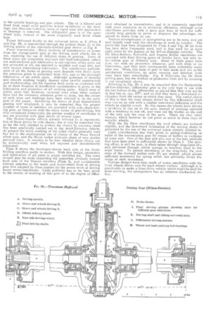
Friction clutehes.—With four of the representative types of under-carriage illustrated, leather-faced cone friction clutches are used, and they continue to be the type most largely employed for transmission of the power from the engine to the driving gear. They either take the form of that shown by Figs. 15 and 16 (see page 127), or they may be of reversed form commonly known as the internal spring pressure balanced type with the directions of movement for engaging or disengaging the opposite of those required with the type illustrated. These two forms equally possess advantages and disadvantages, and there is little reason to adopt one in preference to the other. The clutch cone, as shown by Figs. 15 and 16, may be removed with little disturbance of other parts, Provision for easy removal of the clutch is always necessary.
Clutches constructed entirely of metal and running in oil have been used with very few types of omnibus. That used with the De Dion et Bouton omnibuses is shown in section by Fig. 17. It is of the single-disc type with two. pairs of friction faces ; and it will be seen that the effort of spring engagement is balanced or self-contained. Multiple-disc clutches have been used on some motor omnibuses, and are being used on some that will he ere long running in London and elsewhere. They arc all made on the principle of the Weston clutch,* in which the pressure on one pair of surfaces is brought to bear on any number of such pairs, thus making a given pressure effective over any multiple of pairs of surfaces. Some of these clutches have been used with grooves on the one face and ridges on the other fitting in the grooves as described by Professor Hele-Shawlbefore this Institution, but nearly all are now being made with flat steel annular discs.
Chang:7-speed ,,,ear.---The forms of change-speed gear employed are all similar in that the engagement of pairs of toothed wheels is effected by axial sliding or by side-meshing them. Except for this general similarity they differ in innumerable details as to arrangement, number of wheels, type of bearings, operating gear, form of box, and materials of construction. It may be at once admitted that to deal adequately with the details of these transmission gears a separate paper is required.
An interesting form of gear and one that is largely used is that shown by Figs. 15 and 16 (see page 1271. The wheels shown provide for five speeds, four of which are for forward running. Attention may be directed to the form of the short, stiff shafts (D and E), the types of ball-bearings, and the form and method of securing the gear-wheels to their centre. Those who are not familiar with motor-vehicle construction will no doubt particularly notice the extreme lightness of the cast-iron gear box, and, indeed, the small dimensions of all parts. Judgment can only be pronounced as to the sufficiency of these dimensions, after careful consideration of the nature of the materials employed and the stresses to be resisted.
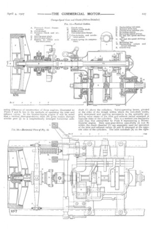
Gear-boxes.—Other forms of gear-boxes are shown by Plates 1, 2, 3, 5 and 6, and Fig. 18 (below), and it will be seen that there is a remarkable difference of size of the containing boxes. The arrangement of shafts and gear wheels in the gear boxes shown by Plates 2, 5 and 6 is such that by using a divided primary shaft two pairs of gear wheels are required for the greater speed reductions. For the highest speed of the omnibus, when the least gear reduction is required, the parts of the primary shaft are connected by jaw clutches. The power is then transmitted through the gear box by the equivalent of a single straight shaft ; none of the gear wheels are active, but are idly driven, iacluding those on the secondary shaft; and frictional losses in the gear box are reduced as long as the top sneed, or direct drive, as it is frequently termed, is in use. When any of the other gears are engaged, the frictional loss is probably greater than that occurring with the type of gear box shown by Figs. 15 and 16 (see page 127), inasmuch as the power is transmitted through two pairs instead of one pair of gear wheels. With the Dennis gear box,the arrangement of the top speed jawclutch is such that simultaneously with its engagement the gear wheel, on the rear end of the primary shaft, which at the lower speeds always transmits the power, is moved out of mesh with its pinion on the lower or secondary shaft. There are then no gear wheels in mesh, and the secondary shaft and the wheels carried by it are stationary. When it becomes necessary to change from the top speed to the next highest speed the stationary secondary shaft has to be accelerated up to proportional speed by re-engagement or side-meshing of the final pair of gear wheAs referred to.
In these gear boxes there are only two shafts, or if the divided shaft is regarded as two shafts, only three shafts with their toothed wheels, and there is in addition a short spindle or shaft cairying one and somrtinnes two pinions used in the train required for reversing. Referring to Plate 1, it will be seen that two gear boxes are employed, the first, that at A, containing the change-sped gear, and delivering the drive through the propeller shaft (C) to the second gear box (B). In this second gear box there is a pair of bevel wheels at B, by means of which the right-angle change of direction of drive is effected, and a pair of spur wheels for a further stage of gear reduction. The larger of the spur whees surrounds the differential gear through which the power is equally delivered to chain sprockets at the ends of the divided transverse shaft. In some forms of gear box, notably that used with the Durkopp and De Dion omnibuses, the change-speed gear, and bevel and differential gears are all contained in a single gear box, thus forming a single complete transmission gear unit, the only separate and exposed gear being, with the Durkopp omnibus, the chains and chain wheels for the final drive to the road wheels. Figs. 18 and 19 below) show the change-speed and differential gear box of this type used with the De Dion omnibuses. The driving pinion Fig. 181 gears with the large bevel wheel (L, Fig 19), so that although separately shown the position occupied by the differential gear may be judged by reference to these views and to
Plate 3. For forward running, power is transmitted from one of the pinions on the upper shaft to one of the corresponding wheels on the lower shaft, the six gear wheels shown providing for three forward speeds. Only one pair of change-speed wheels is engaged at any time, but necessarily a train of two wheels is also included for reversing at low speed. Interesting features of this gear box include the use of an oilcirculating pump (G, Fig. 18), for the continuous supply of oil to the spindle bearings and gear wheels. The cil is filtered and freed from small solid particles before re-delivery to the bear. rugs, and thus one common cause of rapid wear and destruction of bearings is removed. The differential gear is of the spurwheel type, instead of the more frequently used bevel wheel type.
Power delivered finally to the universal joints at E (Plate 3 and Fig. 19), is transmitted through the jointed shafts (j) to the driving pinion of the internally-toothed gear shown in Fig. 9.
Power transmission.--Many methods of transmission of power from the .change-speed gear to the driving road wheels are in use, requiring the use of different types of gearing. Some of these types are completely enclosed and bath-lubricated, others are semi-enclosed and lubrication is not copious, while some are not protected at all, are exposed to weather and road dirt, and only receive intermittent lubrication. The satisfactory performance of all the forms of gearing used depends very much upon the attention given to protection from dirt, and to the thorough lubrication of all active parts. Although quietness of running and smooth working largely depend upon careful construction and workmanship, yet the freedom from noise so conferred will be of short duration if insufficient consideration is given to the lubrication and protection of all working parts. Rapid wear of active parts has, however, occurred even when these matters have had the necessary attention given to them, but the causes of such wear and breakage have been referred to in the early part of the paper. Reviewing the forms of final transmission gearing now employed, it may be remarked that the greater number of types of omnibus are provided with side chain-driving gear, as compared with the many forms of gear-driving, but that considered numerically the greater number of omnibuses in use are provided with gear drives of several types.
The StralKer-Squire vehicle already referred to is representative of those driven by side chains; but it may be remarked that so far the only attempt to protect the chains by encasing them has been practically carried out in the Arrol-Johnston vehicle. At present the noisy working of the roller chains generally used has led to the experimental use of chains of the Hans Renold silent type, and the Morse rocker joint-pin chain of very similar external form. It remains to be seen whether these chains can be economically used when left exposed and intermittently lubricated.
Plate 6 shows the bevel.gear-driven back axle of the Scott. Stirling omnibus partly in section. With this design, protection and lubrication of all parts is amply provided for. The same remark may be made respecting the somewhat similarly formed back axle of the Dennis •omnibus (Plate 21, and considerable interest attaches to the worm and worm-wheel form of driving gear first adopted by these makers for the severe work of driving heavy motor-omnibuses. Little publicity has so far been given to the results of working of this gear or to the degree of effici
ency obtained in transmission, and it is commonly regarded with some suspicion as to economic efficiency, although some omnibuses provided with it have now been at work for sufficiently long periods to prove or disprove the advantages expected to result from its use
Various arrangements of spur-gearing are to be seen, and are now largely used with the omnibuses at work in London. The particular type here illustrated by Plate 4 and Fig. 20 (at foot) has been most frequently used, and is that used for at least eight years by the makers of the Milnes-Daimler vehicles. The De Dion-Routon, Ryknield, and Eugene Brillie omnibuses are provided with final driving gears of similar form, but with intermediate gear of different type. Many of these gears have bren run with no protection whatever, and with little or no lubrication, and they have consequently been noticeably noisy after use. When this form of gear is well made and run under satisfactory conditions, its quiet running and freedom from wear have been remarkable. Fig. 9 illustrates the De Dion driving gear, but the method of protection from dirt by encasing is not completely shown.
Referring to Fig. 20, it may be remarked that the Marienfelde (Milnes-Daimler) differential gear is the only type in use with the two halves of the differential so placed that they may not be in line but at, say, 177°, and sri that they have a downward inclination from the centre at which they meet. The useful object of this is that the road wheels driven by this differential shaft may run on an axle with a similar downward deflection and the wheels be slightly coned. By this means the wheels have always a tendency to run on to the axle, instead of pressing outward with a tendency to run off, and wear out the washer on the end of the axle and the nose of the nave. There are also other reasons, which however do not press so much in these days of metallic wheels.
With the De Dion omnibuses the road wheels are inclined slightly, and the downward inclination of the driving shafts is permitted by the use of the tiniversal joints already referred to Little consideration has been given to spring-cushioning or relief of the transmission gear by means of buffers or cushions of some sort. One of the first and also one of the best methods that have been used is sufficiently shown by Plate I. The driving effort, it witl be seen, is there taken through drag-links (F), and delivered through volute springs to brackets fixed to the main frame. To permit movement of the drag-links the rear ends of the forward radius rods (E) are slotted, which allows sufficient movement for spring relief, but advisedly limits the range of such movement.
Various designs have been made of motor omnibuses with the front wheels driven and the back wheels trailers. Although it is practicable to make a front-drive vehicle which might be used for level running, the arrangement has an inherent mechanical defect. The propulsive effort is in part resolved into a vertical or turning effort about the centre of rotation of the whole, resulting in an increase of the load effect on the back wheels and a decrease on the front wheels. The frictional adhesion is therefore so lessened that acceleration from rest is reduced and hillclimbing troubles increased. Rapid acceleration is more or less a necessity for motor-omnibuses for London use, and rear-wheel propulsion would seem therefore to be a necessity. It may be here mentioned that the same fore and aft tilting effort, but in the opposite direction, occurs on the application of the brakes, and hence the distance within which retardation from velocity to velocity 0 is possible is greater than the distance within which acceleration from velocity 0 to velocity X may be obtained.
Brakes.—Brakes for any motor-vehicles, and perhaps it may bs. said especially for motor-omnibuses, are amongst the most important of the details. In almost all the omnibuses at present running, the brakes chiefly used are those operated by the pedal under the driver's foot, acting on bands or brake-shoes of one type or another, on brake drums attached to one of the gear-box shafts, or to the transverse shafts of both gear and chain-driven omnibuses. In some vehicles the anchorage of the brake-bands or shoes is carried by a member of the frame as at G and Plate 2. By this means the stresses due to the resistance to rotation of the brake-bands is carried by the frame, and the gear-box thereby relieved. These brakes, although on drums of small diameter, are powerful because they are applied to a highspeed shaft, and in many cases are now cast with an internal channel to receive water to keep them cool.
Supplementary to these brakes are thoss on the driving wheels, and they are of several forms. In most cases they are bandbrakes on drums affixed to the wheels, and in some they are internal expanding brakes inside these drums. The internal brake is, for instance, fitted to the vehicles shown by Plates 2, 5, and 6, in which the driving wheels run on a hollow fixed axle. In the form shown by Plate 1, in which the wheels run on a fixed solid axle and are driven by chains, the sprocket wheel and drum are seen between the road wheels and the springs in the plan. In that vehicle the side brakes are of the internal expanding type, applied by a side lever and equalising links at K, through which an equal pull is given to the two side-rods which run backwards to the brake. A different form of equalising brake pull is shown in the plan, Plate 6, in which an equalising bar T is pulled from the centre by the hand-lever and the two side-rods actuated by it. In some vehicles an exterior brakehand is applied to a drum of the kind shown by Plate 1. Fig. 21, herewith, illustrates the pinion or differential brake acting upon the drums II, Fig. 90, and it indicates sufficiently the type of foot-brake used with several vehicles. Cast-iron brake-drums and brake-blocks are used, and in the example shown there is provision for easy adjustment of the blocks and their easy replacement when worn.
Workin! Costs.—All the petrol motor omnibuses dealt with in the paper are of the same carrying capacity, namely 31 passengers, and hence a nearer approach to the actual working costs can be made than is the case with motor wagons, for instance, working in different parts of the country in different trades, different length of journeys, and different effective proportion of journeys, varying loads and varying terminal and stopping-place time losses, working with and without trailers, which give rise to great variation in the relation between cost of working per vehicle-mile and per load ton-mile. With the petrol motor omnibus it is only necessary to consider the cost per vehicle-mile. This varies to an appreciable degree with different makes of motor omnibuses, but this variation is very small as compared with the difference caused by different management. Most omnibus owners started operation with the ownership of little or nothing more than the omnibuses, just as though they were only wheelbarrows and required only a gang of labourers to wheel them, and a ganger to see that they wheeled them. The owners did not understand that they were entering upon an engineering undertaking with an immense quantity of high-class machinery, which would require more constant care and supervision than was ever before required for any similar quantity of machinery, not even excepting the railway locomotive with its requirements of running-shed and engineering workshops. having found that the motor omnibus would run when delivered to theirs, they ran them distances and speeds regardless of the difference between the possible and the commercially practicable or expedient. With no repair works and with insufficient and sometimes incompetent staff, they ran their omnibuses as many hours as they could anyhow be kept on the road and at destructive speeds. In no commercial matter has the adage, as to the stitch in time saving nine, ever proved to be so indisputable a fact. The one stitch was seldom made, until the disastrous results of its disregard proved that the motor-omnibususing company must fully recognise the engineering requirements of the business it enters upon. This has caused great increase in the cost of maintenance over that which was necessary. In the latter part of 1905 and early part of 1906, the author estimated the total working expenses of 34-seated petrol motor omnibuses working a maximum of 90 miles per day at from 8.79d. to 9.0d. per omnibus-mile. Since then petrol has nearly doubled in price, and the unsatisfactory conditions of working have increased the cost of repairs and renewals, and the long mileage per day makes double shift of both driver and conductor, or three drivers and conductors to two omnibuses, necessary. Improvements in the matters affecting repairs and renewals are, however, being made, and there is every probability that this estimate will be fully confirmed by all well-managed omnibus services, as it has already been confirmed by some. The increased price of petrol and the extra cost of double shift and of longer mileage must of course be added to that estimate. The cost of working a petrol motor omnibus of the better makes, under proper conditions and running an average of 100 miles per day for 280 days per year, or 28,000 miles, may now
be put as follows :
The average receipts per motor-bus mile in London exceeds 13d. per mile. The difference botween receipts and the new possible cost of working is thus fully equal to the author's expectations as stated on various occasions.
Conclusion —No standardisation in motor-omnibus construction can be expected for some time. The general design of the motor omnibuses now in use may be said to have been outlined from two to five years before they were developed in detail to the types which began to be used two years ago in any number in London.
The extraordinary mileage, which soon became a possibility with them, rapidly accumulated more working experience in a short time than has probably been crowded into a few months with any other type of road vehicle under commercial conditions. The companies started running them, the public immediately adopted them in preference to the old horse vehicle, and the companies were constrained to keep them on the road in spite of the very great difficulties which accompanied continuous work and continuous necessity for improvements and renewals. The result is now obvious in the great advance which has been made in the last year and a half towards a satisfactory vehicle; but the experience has been very costly, and on the whole it must be admitted it has proved that even with the finest material ever placed in the hands of the mechanical engineer, larger dimensions and greater surfaces are required to contend with
the severe work of the present double-deck omnibus. Some further improvements, which will secure durability of parts and fewer breakages resulting from loosening of parts, will no doubt be made ; but endurance of known materials used under present conditions of working and road surface cannot be indefinitely extended. Improvement may be looked for in the conduct of traffic that will permit, say, twenty-six-passenger omnibuses to be run commercially. Then the weight of an omnibus may be materially reduced, and fuel and oil consumption and wear and tear reduced, and these with a general observance of the legal speed limit will together add to the life of an omnibus, to its trustworthiness and to its commercial efficiency. There are now fewer directions in which imagination can point new paths of improvement, but there are still sufficient to make it unwise to act as though a standard of design and construction had been approached.