


Vehicles in the Trials.
Page 3
Page 4
Page 5
If you've noticed an error in this article please click here to report it so we can fix it.
The Darracq-Serpollet Steamers: C16, C17, D22, and E341.
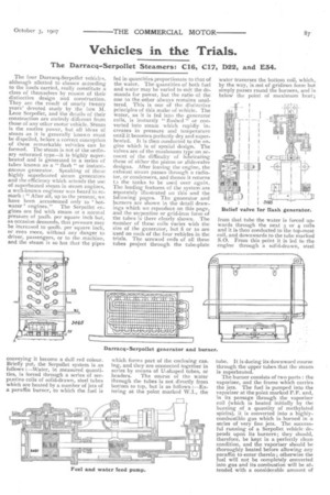
The four Darracq-Serpollet vehicles, although allotted to classes according to the loads carried, really constitute a class of themselves by reason of their distinctive design and construction. They are the result of nearly twenty years' devoted study by the late M. Leon Serpollet, and the details of their construction are entirely different from those of any other motor vehicle. Steam is the motive power, hut all ideas of steam as it is generally known must he dispelled, before a correct conception of these remarkable vehicles can be formed. The steam is not of the ordinary saturated type—it is highly superheated and is generated in a series of tubes known as a " flash " or instantaneous generator, Speaking of these highly superheated steam generators and the efficiency which attends the use of superheated steam in steam engines, a well-known engineer was heard to remark : " After all, up to the present, we have been accustomed only to hotwater' engines." The Serpollet engines are fed with steam at a normal pressure of 300lb. per square inch but, as occasion demands, that pressure may be increased to goolb. per square inch, or even more, without any danger to driver, passengers, or to the. machine, and the steam is so hot that the pipes
conveying it become a dull red colour. Briefly put, the Serpollet system is as follows :—Water, in measured quantities, is forced through a series of serpentine coils of solid-drawn, steel tubes which are heated by a number of jets of a paraffin burner, to which the fuel is
fed in quantities proportionate to that of the water. The quantities of both fuel and water may be varied to suit the demands for pol,ver, but the ratio of the one to the other always remains unaltered. This is one of the distinctive principles of this make of vehicle. The water, as it is fed into the generator coils, is instantly " flashed " or converted into steam which rapidly increases in pressare and temperature until it becomes perfectly dry and superheated. It is then conducted to the engine which is of special design. The valves are of the mushroom type on account of the difficulty of lubricating those of either the piston or slide-valve designs. After leaving the engine, the exhaust steam passes through a radiator, or condensers, and thence it returns t.) the tanks to be used over again. The leading features of the system are separately illustrated on this and the following pages. The generator and burners are shown in the detail drawings which we reproduce on this page, and the serpentine or grid-iron form of the tubes is there clearly shown. The number of these coils varies with the size of the generator, but 8 or io are used on each of the four vehicles in the trials. The screwed ends of all these tubes project through the tube-plate
which forms part of the enclosing casing, and they are connected together in series by means of U-shaped tubes, or
headers. The course of the water through the tubes is not directly from bottom to top, but is as follows :—Entering at the point marked W.I., the water traverses the bottom coil, which, by the way, is not of gridiron form but simply passes round the burners, and is below the point of maximum heat ;
from that tube the water is forced upwards through the next 3 or 4 coils and it is then conducted to the top-most coil, and downwards to the tube marked S.O. From this point it is led to the engine through a solid-drawn, steel
tube. It is during its downward course through the upper tubes that the steam is superheated. The burner consists of two parts : the vaporiser, and the frame which carries the jets. The fuel is pumped into the vaporiser at the point marked P.F. and, in its passage through the vaporiser coil (which is heated initially •by the burning of a quantity of methylated spirits), it is converted into a highlycombustible gas which is burned in a series of very fine jets. The successful running of a Serpollet vehicle depends upon its burners ; they should, therefore, be kept in a perfectly clean condition, and the vaporiser should be thoroughly heated before allowing any paraffin to enter therein ; otherwise the fuel will not be completely converted Into gas and its combustion will be attended with a considerable amount of smoke and soot which will result in the choking of the jets.
Such a high degree of superheat completely barred the employment of any ordinary form of relief-valve in connection with the generator. The 4)ne shown on page 87 is the one which has been designed to meet the special .requirements. It consists of two parts, one of which is connected as a shunt from the water-pump, delivery pipe to the condensers; the other is connected in series with the pressure gauge. The pressure in the pipe leading to the latter acts on the plunger (P) above which is a strong, helical spring (R). When the plunger (P) is forced upwards by the pressure in the generator, the spindle (T) causes the spindle (N) to be lifted through the medium of the trigger (M). This causes a ball-valve in the chamber (C) to be lifted off its seat and thus to allow some of the delivery water to return to the condensers by way of the union (D), the passages (F and C), and the union (G). This relief-valve, in conjunction with the
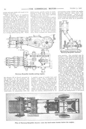
donkey-pump, greatly assists in maintaining a fairly even head of steam and protects the tubes from splitting through excessive pressure. A hand-worked water-pump is used to feed the first few charges of water into the generator, but immediately a few pounds pressure has been reached, the donkey-pump, shown on page 87, comes into action. It will be seen that the steam-piston is in a direct line with the water-plunger and that the pistonrod is screwed directly into the waterpump plunger. Above the water-pump, and operated by the same rockinglever which actuates the steam-valve, is another pump of smaller bore and shorter stroke : this is employed for feeding paraffin to the burners in the proportion of about one of fuel to 9 of water. After having been adjusted for each particular vehicle, the proportion of oil to water is never altered.
Now, turning our attention to the engine and gearing, it will be seen clearly from our illustration above, that they are entirely self-contained in an
oil-retaining casing. Unlike the earlier Serpollet engines, these have two, double-acting pistons. Steam is admitted to the cylinders past mushroomvalves which are operated from a camshaft much the same as in petrol-en gine practice. The camshaft may be caused to slide longitudinally and, by this means,' the point of cut-off may be varied at will, or the engine may be very readily reversed. The camshaft is driven through spur-gearing from the crankshaft, as is also the differential countershaft. From the outer ends of the latter, the side-chain sprockets are driven through Oldham couplings. From the chain sprockets, the engine power is transmitted to the rear roadwheels through Morse silent chains.
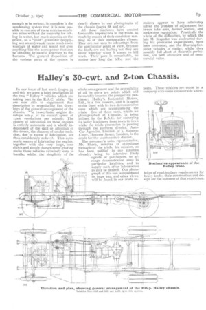
After being exhausted from the engine, the steam is passed on to the condensers, of which there are three : the first one is really a multitubular„ feed-water heater. From this point, the exhaust steam passes to a second condenser situated under the after part of the chassis, and from thence to a large, gilled-tube radiator or condenser in front of the vehicle. The exhaust pressure is relied upon to force the water through the condensers, but, as the first one is a rnultitubular, in parallel, the back-pressure is not great
enough to be serious. So complete is the condensing system that it is now possible to run one of these vehicles nearly too miles without the necessity for taking in water, but much depends on the driver, as a "cold" generator (supplying wet steam) would cause much more wastage of water and would not give anything like the same power that can be obtained by careful attention to the burners. The general disposition of the various parts of the system is clearly shown by our photographs of the chassis (pages 88 and 92). All these machines have created favourable impressions in the trials, as much by reason of their consistent running as of their comparative silence, They are not seen to advantage from the spectacular point of view, because the loads are not bulky ; but they are never wanting when it comes to hill work. Their pace is remarkable, no matter how long the hills, and the makers appear to have admirably solved the problem of adjustment hetween tube area, burner control, and feed-water regulation. Practically the whole of the difficulties, by which the late M. Serpollet was confronted during his protracted experiments, have been overcome, and the Darracq-Serpollet vehicles of to-day, whilst they possibly fall short of theoretic perfection, are both attractive and of commercial. value.