


Simplifying Cylinder-head Castings
Page 36
If you've noticed an error in this article please click here to report it so we can fix it.
A Résumé of Patent Specifications that Have Recently.
Been Published •
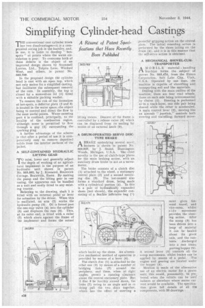
THE conventional cast cylinder block has two disadvantages—it is a complicated coring job in the foundry, and, in use, it is liable to develop " hotspots" at points where the water circulation is poor. To overcome both of these defects is the object of an improved design shown by Scammell Lorries, Ltd., Tolpits Lane, Watford West, and others, in patent No. 563,789.
In the proposed design the cylinder head is cast with an open top, which not only makes for a simplified casting. but facilitates the subsequent removal of the core. In assembly, the top is closed by a screwed-on lid (I) fitted with a suitable packing washer.
To remove the risk of the formation of hot-spots, a deflettor plate (2 and 3) is located in the water space, -the object being to control and direct the flow to the most useful points. Water entering port 4 is confined, principally, to the locality of the combustion region, although some is permitted to flow through a gap (5) surrounding the sparking plug. A further advantage of the scheme is that after a period of use it is comparatively easy to remove depoiitekl solids from the interior surfaces of the jacket.
A SELF-CONTAINED HYDRAULIC LIFTING GEAR
Traise, lower and generally adjust the depth of working of an agricultural implement is the purpose of an hydraulic unit shown in patent No. 563,802, by J. Kinnaird, Braiswick Cottage, Braiswick,. Essex. By making the pump and the lifting gear in one casing, the apparatus can be handled as a unit and easily fitted to any existing tractor.
Referring to the drawing, shaft 1 is fitted with an external pedal or lever for actuation by the driver. When this is oscillated, an arm (2) works the hydraulic pump (3). Oil is forced past the one-way valve (4) into the cylinder (5) and displaces the ram (6). -This. at its outer end, is fitted with a roller (7) which abuts against the frame of the implement and forms the actual lifting means. Descent of the frame is controlled by a release valve (8) which can be displaced from its seating by means of an external knob (9).
A DRUM-OPERATED SERVO DISCTYPE BRAKE
ABRAKE em-bodying several novel features is shown in patent No 563,927, by J. Sneed, Huntington Woods, Michigan, U.S.A. The -chiefnovelty is the use of clutch-type -plates for the main braking action, with an auxiliary drum brake to act as a-servomotor.
The brake consists of a clutch disc (1) attached to the wheel, a stationary central plate (2) and a second revolving disc (3). The last-named also forms a standard drum, being made with a cylindrical portion (4). In this is a pair of hydraulically expanded shoes (not shown), the expander consisting of a flexible inflatable bag (i) which backs up the shoes, An alternative mechanical method of operation is provided by means of a lever (6).
The clutch disc (1) is attached to the other one (3) by means of a number of bridging links .(7) . around the periphery, and these, when at right angles, permit a running clearance about the central stationary plate. But if disc 3 be forcibly slowed down, the links (7) swing to an angle and in FO doing pull the two discs together, which has the effect of exerting a powerful gripping action on the central plate. The initial retarding action is performed by the shoes acting on the drum (4), and it is in this manner that
self-servo action is obtained.
A MECHANICAL SHOVEL-CUMTRANSPORTER A MOBILE material handling inachine forms the subject of patent. No. ,563,474; from the Eitnco Corporation, Salt Lake City, Utah, U.S.A. Operated by one man, the machine is capable of shovelling and transporting soil and like materials, Dealing with the main outline of the machine; there are four road wheels, those on each side being interconnected by chains (I). Steering is performed as in a track-layer, one side pair being slowed while the other is accelerated. A main control lever (2), moving like an aircraft " joystick," controls both steering and travelling; forward move ment gives forward travel, and
vice-versa, whilst side movement provides the steering action. After the scoop (3) has been driven into a heap of material it can he hauled about its pivot axis, and the contents discharged intoa rear transporting hopper (i4). A second lever (5) controls all the scoop movements, whilst brakes can be applied by means of a pedal. The engine and gearing are located under the hopper (4).
Mention is made of the alternative use of an electric motor for a powei unit; this would, presumably, be preferred when the vehicle can be used indoors or elsewhere where mains cur. rent would be available. The specification gives full details of all the components, with 26 drawings.