 1
1 2
2 3
3 4
4 5
5 6
6 7
7 8
8 9
9 10
10 11
11 12
12 13
13 14
14 15
15 16
16 17
17 18
18 19
19 20
20 21
21 22
22 23
23 24
24 25
25 26
26 27
27 28
28 29
29 30
30 31
31 32
32 33
33 34
34 35
35 36
36 37
37 38
38 39
39 40
40 41
41 42
42 43
43 44
44 45
45 46
46 47
47 48
48 49
49 50
50 51
51 52
52 53
53 54
54 55
55 56
56 57
57 58
58 59
59 60
60 61
61 62
62 63
63 64
64 65
65 66
66 67
67 68
68 69
69 70
70 71
71 72
72 73
73 74
74 75
75 76
76 77
77 78
78 79
79 80
80 81
81 82
82 83
83 84
84 85
85 86
86 87
87 88
88 89
89 90
90 91
91 92
92 93
93 94
94 95
95 96
96 97
97 98
98 99
99 100
100 101
101 102
102 103
103 104
104 105
105 106
106 107
107 108
108 109
109 110
110 111
111 112
112 113
113 114
114 115
115 116
116 117
117 118
118 119
119 120
120 121
121 122
122 123
123 124
124 125
125 126
126 127
127 128
128 129
129 130
130 131
131 132
132 133
133 134
134 135
135 136
136 137
137 138
138 139
139 140
140 141
141 142
142 143
143 144
144 145
145 146
146 147
147 148
148 149
149 150
150 151
151 152
152 153
153 154
154 155
155 156
156 157
157 158
158 159
159 160
160 161
161 162
162 163
163 164
164 165
165 166
166 167
167 168
168 169
169 170
170 171
171 172
172 173
173 174
174 175
175 176
176 177
177 178
178 179
179 180
180 181
181 182
182 183
183 184
184 185
185 186
186 187
187 188
188 189
189 190
190 191
191 192
192 193
193 194
194 195
195 196
196 197
197 198
198 199
199 200
200 201
201 202
202 203
203 204
204 205
205 206
206 207
207 208
208 209
209 210
210 211
211 212
212 213
213 214
214 215
215 216
216 217
217 218
218 219
219 220
220 221
221 222
222 223
223 224
224 225
225 226
226 227
227 228
228 229
229 230
230 231
231 232
232 BEARDMORE OIL ENGINES
Page 147
If you've noticed an error in this article please click here to report it so we can fix it.
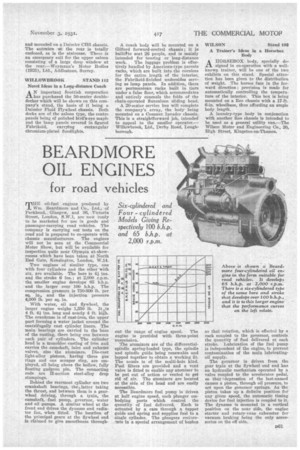
for road vehicles
TE oil-fuel engines produced by Wm. Beardmore and Co., Ltd., of Parkhead,. Glasgow, and 80, Victoria Street, London, S.W.1, are now ready to be marketed for use in goads and passenger-carrying road vehicles. The company is carrying out tests on the road and is prepared to co-operate with chassis manufacturers. The engines will not be seen at the Commercial Motor Show, but will be available for inspection quite near Olympia at, showrooms which have been taken at North End Gate, Kensington, London, W.14.
Two engines of similar type, one with four cylinders and the other-with six, are available. The bore is 41 ins. and the stroke 6 ins.; at 2,000 r.p.ixt. the smaller engine develops 65 b.h.p. and the larger over 100 b.h.p. The compression pressure is 750-800 lb. per sq. in., and the injection pressure 4,000 lb. per sq. in.
With water, oil and flywheel, the larger engine weighs 1,350 lb. It„is 4 ft. 41 ins, long and nearly 4 ft. high. The crankcase is of cast-iron, the upper part forming a water jacket around the centrifugally cast cylinder liners. The main bearings are carried in the base of the casting, there being one between each pair of cylinders. The cylinder head is a monobloc casting of iron and carries the-camshaft, inlet and exhaust valves' also the atomizers. Die-cast light-alloy pistons, having 'three gas rings and one scraper ring, are employed, all being above the hollow, fully floating gudgeon pin. The connecting rods are H-section steel-alloy drop stampings.
Behind the rearmost cylinder are two crankshaft bearings, the ,latter taking the thrust, and between them is a gearwheel driving, through a train, the camshaft, fuel pump, governor, water and oil pumps. A similar wheel at the front end drives the dynamo and radiator fan, when fitted. The location of the principal gears at the flywheel end is claimed to give smoothness through out the range of engine speed. The engine is provided with three-point suspension.
The atomizers are of the differentialspindle spring-loaded type, the spindle and spindle guide being renewable and lapped together to obtain a working fit. The nozzle is of the multi-hole kind. Fuel filters are provided and a vent valve is fitted to enable any atomizer to be put out of action or vented to get rid of air. The atomizers are located at the side of the head and are easily accessible.
The Beardmore fuel pump is driven at half engine speed, each plunger embodying ports which control the quantity of fuel delivered. Each is actuated by a cam through a tappet guide and spring and supplies fuel to a single cylinder. The plungers reciaroTate in a special arrangement of bushes
so that rotation, which is effected by a rack coupled to the governor, controls the quantity of fuel delivered at each stroke. 'Lubrication of the fuel pump is independent of the engine, to prevent contamination of the main lubricatingoil supply.
The governor is driven from the gear Vain at the flywheel end and has an hydraulic mechanism operated by a valve coupled to the accelerator pedal, so that 'depression of the last-named causes a piston, through oil pressure, to act upon the governor springs. As the piston takes up a definite position for any given speed, the automate timing device for fuel injection is coupled to it. The dynamo is mounted in a vertical position on the near side, the engine starter and rotary-vane exhauster for vacuum braking being the only accessories on the off side.