


Patents Completed.
Page 34
If you've noticed an error in this article please click here to report it so we can fix it.
Complete specifications of the following patents will be sent to any address in the United Kingdom by the Sales Branch, Patent Office, Holborn, W.C., upon receipt of eightpence per copy.
A Tube Coupling.
W. Berryman, No. 10,440, dated 2nd May, 1912.—This specification describes an improved form of tube coupling in which the spigot and faucet por
tions are provided with a pin and slot respectively to form a bayonet joint. The pin has a head on it, and the slot is wider at one end to permit the insertion of the pin, which is then moved into the narrow part of the slot. A locking ring, which has a spring catch, is also mounted on the faucet. This is provided with a slot through which the locking pin passes. After the joint has been made, the locking ring is moved round so that. it holds the pin in the narrow end of the slot, and in that position is itself held by the spring catch, and cannot be released until the finger piece of the spring catch is pressed back.
Novel Cooling Methods.
A. H. Adams, E. de Normanville, and Adams Manufacturing Co., Ltd., No. 7344, dated 26th March, 1912.--The efficiency of a radiator is considerably improved by blowing air through the water contained in it. If the air is under considerable pressure, an additional cooling effect. is obtained by its expansion. A small compressor is fitted to the front of the engine to supply air to a reservoir, from which it is taken through an automatic controlling valve, and is injected into the water at the bottom of the radiator. The air is led off by a pipe from the top of the radiator into a cup provided with baffles to collect any water carried over. The air may be cooled by a separate cooling coil to condense any water vapour and prevent loss. The automatic valve is shown in the second figure. A closed chamber is filled with mercury or other liquid, and has a flexible diaphragm at the top which operates a ball-valve. When the circulating water gets warm, the valve is lifted off its seat.
A Colonial Cooling System.
Daimler M.G., No. 19,753/1912, dated tinder International Convention, let September, 1911.—In vehicles that are required for very hot climates, or that run at very low speeds, it is necessary to make provision for a much larger volume of cooling water than is usually the case. According to this specification two radiator tanks are provided, one at each end of the engine, and both tanks communicate by pipes from near the bottom, with a storage reservoir from which the circulating pump draws its supply. In the form illustrated, the hot water is delivered from the cylinders into a main.
Crank-chamber Lubrication:
H. F. Maranville, No. 11,321, dated 13th May, 1912.—Difficulty is experienced with engines in which splash lubrication is used, owing to the unavoidable leakage of hot exhaust gases into the crank chamber. This causes overheating of the oil, and is generally prevented by providing " breathers " or outlets from the crank chamber, The consequence is, that air is sucked in on the up stroke of the pistons and carries with it dirt and other objectionablo matter. The accompanying drawing shows in section a particular form of " breather " which forms the subject of the i,ressait invention. A side chamber is provided at the bottom of the crankcase, and the gases pass into it over a baffle plate which separates the oil. They afterwards pass upwards through a strainer to a hood, pointing towards the rear of the engine, and so escape. The motion of the vehicle, and the action of the cooling fan, causes a constant flow of air past the outside of this hood, so that an ejector action is obtained. This assists in drawing out the exhaust gases.
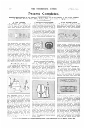
An Oil Storing Chassis.
W. L. Spence, No. 14,045, dated 17th June, 1912.—The accompanying drawing shows a chassis frame in which the side members are of full box or flattened tubular section. Dished ends are provided for these boxes so that receptacles suitable for use as petrol or oil tanks are obtained. Suitable brackets and crossmembers are welded or clamped on to the frame sides to carry the gearbox and other fittings. The tanks are preferably welded from sheet metal by spot welding or some similar process, and a small service or feed tank is provided at a higher level, suitable pipe connections being made between the two. When the car is in motion the feed up to the service tank is maintained by the wave or water hammer action created in the main tanks by the motion of the vehicle. The fillers for the main tanks are preferably situated about the middle of their length.
Silent Chain with Guide Discs.
H. RenoId and Hans Renold, Ltd., No. 20,318, dated 16th September, 1912. —In silent driving chains which are provided with guide links on each side, or in the middle to engage the sprockets and prevent the chain coming off sideways, the guide links are of greater depth than the driving links, and difficulty is experienced in designing them so that their extension under load shall be the same as the other links. There is also a tendency for the pin, when being riveted on, to bind on the guide links, se that it cannot turn, and wears unevenly. These dill. ciilties are now got over by using comparatively large washers or discs on the pin so that they are made to rotate by frictional contact with the sides of the sprocket wheel. All the elements in each link can therefore be the same size and the guiding effect is still obtained by means of the washers. The frictional contact of the washers with the sprocket wheel causes a continual slow rotation, so that the pins undergo uniform wear.