


Patents Completed.
Page 24
If you've noticed an error in this article please click here to report it so we can fix it.
SPEED INDICATOR. — Abell. —No. 16,829, dated 25th July, 1906.—This is a combined centrifugal and friction device. The driving shaft (23) carries a wheel (22e which gears with a pinion (I5). The pinion (15) drives a member (le carrying weights (3), which are free to slide radially therein. Surrounding the member (1) is a dished member (6), which is suitably pivoted a_nd controlled by a spring (11). According to the speed at which the shaft (23) rotates, the weights will bear with greater or less force against the member (6), whereby this will be carried round a greater or less distance. A pointer (10) is connected to the spindle of the member (6) and thus indicates the speed of the shaft (23), and consequently the vehicle or machine wherewith it may be used. A worm (16) on the spindle of the pinion (15) may be connected to any suitable adding device.
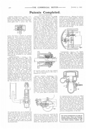
CARBURETTER. — Linley. — No. 24,192, dated 23rd November, 1905—The object of this device is to provide a forced draught for a carburetter. A pump barrel (A) is provided with a plunger (B), which is connected to the 2-to-I shaft. The barrel has, at its lower end, ports (C), whereby the interior may be thrown into communication with the atmosphere, and within the plunger is a chamber (B1), wherewith conduits (H), extending through the wall of the plunger, communicate. An annular passage (F) is formed in the face of the barrel, and is so arranged relatively to the ports (C) that when the plunger is down, these are closed, and the orifices (H) communicata with the channel (F). This channel is in communication, by a conduit (G), with the fuel nozzle (L). It follows that as
the plunger (B) rises, air is admitted beneath it by the ports (C) into the space (Al) of the barrel (A), and as the plunger descends, the ports (C) are closed and the air is trapped and compressed in the chamber (B1). As soon as the orifices (13! register with the channel ;Ft, this air passes to the fuel nozzle, and provides the forced blast.
STUFFING BOX.—Kugel.—No. 24,799, dated 1905, (under Convention, 30th November, 1904).—The object of this device is to so arrange the packing for a rotary shaft that the pressure of the working fluid shall not cause -the packing to bear with undue force upon the shaft. The shaft (c) has a shouldered portion ((c1), and on the shaft and adjacent to the shoulder are collars (d), having radial flange's. Surrounding these collars, and interposed between the radial flanges are other flanged rings (It), which are carried between a surrounding ring (1) and a screw-threaded ring (it). The ring 01) has an annular extension whereon bears a cup leather (p), and the front portion of the stuffing box which is in communication with the fluid pressure chamber connects this with a space (a) at the back of the packing rings by a conduit for the purpose of equalising the pressure on both sides of the packing rings. By this means undue friction between the rings .(p) and collars (d) is avoided, and the pressure of the fluid upon the cup leather does not affect the shaft, as the leather bears upon -FRONT DRIVE.— Brightmore. — No. 1,027, dated 15th January, 1906.—The steering wheels are carried in bearings supported by springs from the under frame (d). The axle is provided with differential gear (c), driven from a countershaft (r) carried in bearings on the main frame. The counter-shaft is driven from the motor by a worm (p), and the wheel axle is connected to the counter-shaft by radius rods (s). The frame (d) is carried beneath the body of the vehicle by a ball socket joint (f) and a curved guide plate (g). The guide plate is provided with teeth (ki and a pinion (1), carried by the frame (di gears therewith. The steering is effected by means of this pinion, which is connected to the motor shaft by a worm shaft whereon bevel pinions (u and y) are mounted. These pinions are free on the shaft, and are geared together by inter mediate pinions Ise Between the pinions (a and y) is a. clutch member, whereby either pinion may be rigidly connected to the shaft. The pinion (y) is made to bear against a friction member (I) on the driven shaft by a spring, and the operator, by moving the clutch member into engagement with one or other of the pinions thus effects the steering.
VAPORISER.— Greves. —No. 10,571, dated 5th May, 1906.—The vaporising chamber (A) is fed with fuel by a conduit (131 and is heated by any suitable means. It is found in practice that the vaporiser usually gets too hot, and the object of this invention is to maintain it at a proper working temperature. For this purpose the chamber is provided with a surrouriding annular space (C), into which the water is admitted by a valve (E). The air for the explosive charge is admitted by a channel (C) above the restricted mouth of the chamber (A), and the annular space
(C) communicates by a series of orifices (D) with the mouth of the chamber. The water enters the mouth of the chamber by the orifices (D), and becomes converted into steam, whereby the temperature of the vaporiser fuel is reduced. The steam and vaporised fuel then meet the incoming air, and the steam is condensed, and falls back into the chamber (A), whilst the fuel passes on with the air into the cylinder. It is stated that the condensed steam being returned to the chamber (A) prevents decomposition of the fuel.