


WELDING AS AN AID T( /EHICLE MAINTENANCE
Page 26
Page 27
Page 28
If you've noticed an error in this article please click here to report it so we can fix it.
THE repair by welding of such components as cylinder blocks, craukcases, crankshafts, exhaust pipes, manifolds, bumpers, windscreen frames, carburetters, wings and chassis frames, in fact almost every part of a motor vehicle, has had the effect of lowering the cost of maintenance, increasing the efficiency of repair work and, during the present vital period, has assisted maintenaonce engineers in giving a longer life to working parts, whilst the standing time for overhauls has been decreased. In point of fact it has enabled components to be salvaged which, otherwise, would have been scrapped and which, in any. case, are in short supply, or wholly unobtainable.
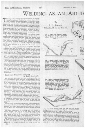
• Fig. 1 shows a cylinder block which was crached almost completely around the casting, as indicated. The block was dismantled and cleaned, and the crack was marked with red pencil. It was then put into a gas furnace and brought to a dull-red heat all over; under the application of heat • the red-pencil marking turned white, showing .the exact position of the crack to be welded. The weld was started at the spot indicated by a cross in Fig. 1 an welded outwards.
• After the welding operations 'were complete, the block leas again put into the furnace and brought to a red heat. The gas was then turned off and the casting allowed to cool down in the hot atmosphere. When quite cool, the top was
e lightly run over on a Pla,nitor-type grinding machine and it was found that no distortion had taken place. It was then tested for soundness of weld and found to be quite successful. This repair enabled the vehicle to go back into service, whereas it would, most probably:, have had to remain out of COMITliSSi011 until after the war.
With east-iron welding of this type the greatest difficulty lies in the expansion and contraction of the 'metal, but, so long as this problem be given careful consideration, no difficulty should be experienced. The operator, however, must, be fully conversant with the practice of welding cast iron. To weld this metal the following, points should be kept in mind:—When cast iron is heated and allowed to cool rapidly, the carbon has not sufficient time to form as graphite, therefore it remains in the combined form known as cementite.
Cast Iron Should be Allowed to Cool Gradually The resultant cast iron is hard and brittle, possessing low tensile strength and, when fractured, shOws a smooth, white, granular structure. However, if the metal be allowed to cool in the atmosphere of an annealing furnace, the carbon has time to adjust itself as graphite, producing grey cast iron which is soft and ductile, with a higher tensile strength, and which, when fractured, shows a rough, granular structure.
Cast iron, when molten, oxidizes rapidly. It Commences to oxidize at red heat, the meltirrg point of this oxide being Approximately 200 degrees C. above that of the metal (1,150 degrees C.). Also, cast iron is very fluid when molten, and this fluidity is the cause of gases, oxide and dirt being entrapped in the molten metal. However, thiS can be-overcome by correct manipulation of blowpipe and filler rod.
A good flux is essential when welding cast iron, in order to cleanse the weld metal and dissolve the oxide and float it to the surface. Care must be taken to use this flux sparingly, as an excess tends to produce hard and brittle welds.
To-day, there are several types of filler rod on the market, the most popular for general work being ferro-silicon. Supersilicon ig used where a soft machinable surface is required, and the 3 per cent. iiickel-alloy rod when building up worn surfaces.
The flame adjustment for welding cast iron should be strictly neutral, and the tip 'of the whitecone is held approximately ek in. to in. away from the molten pool. The reason -for this is to prevent the formation of hard spots, which would result if the white, cone be allowed tit impinge on the metal while in its molten, state.
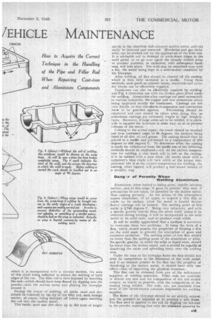
On thicknesses over in, the material should be bevelled in single vee formation having an included angle of 90 degrees, On thicknessee over • in. double bevelling is employed, two unequal 90-degree vees being formed, one
being two-thirds through from one side, and the .second through from the other side (see Fig. 2). All large sections should he pre-heated in a innfile before welding.
The angle ot the blowpipe should be kept as steep as possible in order to prevent the fluid metal from being blown forward to the unmelted part, of the weld seam, thus causing adhesion. This angle varies between 70 degrees and 90 degrees, according to the position of welding, whilst the angle of the filler rod fluctuates between 40 degrees and 50, degrees (see Fig. 3). The blowpipe flame is played upon the start of the weld antil the metal becomes molten; after
which it is manipulated with a circular motion, the area of this circle being sufficient to ensure the melting of both edges of the vee. The filler rod is then impased by inserting the end—which should have been fluxed by dipping into the powder—into the molten metal and playing the blowpipe around it.
During the course of welding, all oxide, sand and, dirt should be removed by the tip of the filler rod, such foreign matter, of course, being knocked off before again inserting the rod into the molten metal, This'axide, sand and dirt show up in the form of bright specks in the otherwise dull-coloured molten metal, and can easily be detected and removed. Blowholes and gas inclusions can be worked out by the application of the filler rod. It is advisable not to atttempt to work-down ridges in the . weld metal, or to go over again the already welded areas to produce neatness, as oxidation, with silbseqttent hardness, will take place. The weld may be smoothed over with a file, the metal being kept in a seini-molten condition by the blowpipe.
After welding, all flux should be cleaned off the casting, which is then fully annealed in a muffle. Using these methods, such parts as cylinder heads, manifolds and cylinder blocks can be effectively repaired.
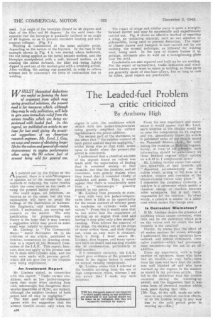
Crankcases can also be effectively repaired by welding. and 'Fig. 4 illustrates one with thd broken piece fitted ready for welding,. Aluminium-alloy castings are used extensively , in various industries, the copper and zinc aluminium alloys .beinat. employed mostly for crankcases. Castings are riot veryductile, so that the effects of expansion and contraction have to be guarded against. Pre-heating should be employed and .care should be taken when doing this, as aluminium castings are extremely fragile at high temperatures. Moreover, if large areas are to be welded, it is advisable to support the structure in some way, so as to prevent collapse of the metal.
Coming to the actual repair, the crack should be bevelled out to.a contained angle of 90 degrees, the surfaces being freed of all dirt, oil and grease. The casting should then be• placed in a muffle and pre-heated to a temperature of 370 degrees to 430 degrees C. To determine when the casting is ready for withdrawal from the muffle one of the following methods should be employed:—(1) At the correct temperature for welding, a char mark will be left on the casting, if it be rubbed with a pine stick; (2) marks made with a carpenter's blue chalk will then white at the proper temperature; (3) if at the correct temperature for welding, the casting, when tapped, will produce a dull sound instead of a metallic ring.
Dangsr of Porosity When Welding Aluminium Aluminium, when heated to fusion point, rapidly becomes
molten, and at this stage, if a be present, they may, if precautions be not taken, be absothed by the molten metal, thus causing -porosity. As the action of the atmosphere causes aluminium, of all types, to acquire a thia film of oxide on its surface, when the metal is heated further heavy coatings will be formed. The melting point of this oxide is 24745 degrees C. Being very refractory, and with a specific gravity heavier than the metal itself, unless it be removed during welding, it will be incorporated in the weld. metal in its solid state, and so produce weak welds, It will be readily appreciated that a medium is necessary . to overcome these two problems. It takes the form of a flux, which should possess the properties of forming a film on the weld seam to prevent the -absorption of gases and excessive oxidation. The melting point of this flux should be lower than the melting point of the aluminium or alloy. Its specific gravity, in either the solid or liquidstate, should be lower than the molten metal, and it should' be capable of dissolving the oxide and .spreading. freely over the welding area.
Under the heat of the blowpipe flame the flux should not alter its composition to the detriment of the weld metal, and if an element present in the flux has the property of dissolving in the molten metal, it should have only one effect—that of improving the physical structure.
This flux can be obtained from any of the well-known suppliers of welding materials. Filler rods are available in almost any size and the composition of the rod should comply, as nearly as possible, with the composition of the casting being welded. The rods, too, are available from most of the better-known concerns responsible for welding supplies.
The flame of the blowpipe should. be set strictly neutral and the pressure so adjusted as to produce a soft flame. The flux used is applied to the rod by dipping the bat-end in the powder, ensuring that only the minimum quantity be used. Lie angle of the blowpipe should be 95 degrees and that of the filler rod 30 degrees. As the weld nears the opposite end the blowpipe is gradually inclined to an angle of 40 degrees, so as to prevent excessive heating and subsequent collapse. (Fig. 5.) ,
Welding is commenced at the most suitable point, depending on the nature of the fracture. In the' case of the example shown in Fig. 4 it was started where indicated, the rod being applied as the metal became molten, and the blowpipe manipulated with a soft, forward motion, as if coaxing the metal forWard, the filler rod being lightly dipped in and out of the molten pool with a brushing action. After welding, the casting was annealed, in order to relieve stresses and tocounteract the force of contraction due to welding.
The repair of wings arid similar parts is quite a straightforward matter and may be successfully and expeditiously carried out. Fig. 6 shows an effective method of repairing a wing, an insulating material, such as wet asbestos or aldernoldite, being used to prevent distortion. The repair of chassis frames and bumpers is best carried out by am welding, the normal technique, as followed for welding steel, being used. In the case of chassis frames it is, perhaps, advisable also to weld on ae strengthening. plate over the weld.
Crankshafts are also repaired and built-up by arc welding. For the repair of carburetters, traffic indicators and windscreen frames, care must be taken in welding, as these parts are generally made of zinc-base.alloys, but so long as care be taken, good repairs are practicable. -