


Springing for Twin-tyred Vehicles
Page 64
If you've noticed an error in this article please click here to report it so we can fix it.
PATENT No. 685,745, which comes from Daimler Benz A.G., Stuttgart -Untertiirkheim, Germany; expounds certain views on the action of
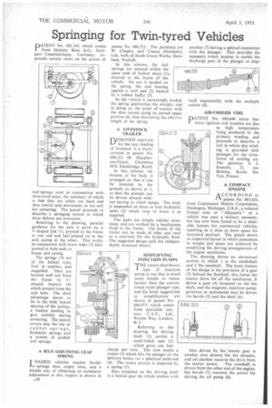
leaf-springs used in conjunction with twin-tyred axles, the summary of which is that they are either too hard and thus restrict axle movement, or too soft for cornering. The patent proceeds to describe a springing system in which these defects are overcome.
Referring to the drawing, parallel guidance for the axle is given by a V-shaped link (1), pivoted to the frame at one end and ball-jointed on to the axle casing at the other. This works in conjunction with lower links (2) balljointed at both ends to frame and casing.
The springs (3) arc of the helical type, four in number, and unguided. They are located well out from the frame by Ushaped bearers (4) which project from the axle tube. The chief advantage seems to lie in the wide lateral spacing of the springs, a feature tending to give stability during cornering. The patent covers also the use of rubber springs, hydraulic springs and a system of guided coil springs.
A SELF-ADJUSTING LEAF SPRING
I OADED vehicles require harder -I" springs than empty ones, and a Simple way of obtaining an automatic adjustment in this respect is shown in
A38 patent No. 686,725. The patentees are W. Chaplin and Cranes (Dereham), Ltd., both of South Green Works, Dereham, Norfolk.
In this scheme, the leaf springs arc entered within the open ends of hollow shoes (1)., secured to the frame of the vehicle. No eye is needed on the spring, the end bearing against a steel pad (2) backed by a rubber buffer (3).
As the vehicle is increasingly loaded, the spring approaches the straight, and in doing so, the point of "contact with the shoe travels along its curved upper portion (4), thus shortening the effective length of the spring.
A LIVESTOCK TRAILER
DESIGNED expressly for the easy loading of livestock is a trailer covered in patent No. 686,321 (R. Macpherson-Grant, Christmas Mill, Edenbridge, Kent).
In this scheme, the bottom of the body is arranged ,so that it can be lowered to the ground, as shown at I. so that the animals can be driven aboard without having to climb ramps. The body is suspended on three or four hydraulic jacks (2) which raise or lower it as required.
The jacks are simple tubular structures, and arc worked by a hand-pump fixed to the frame. The frame of the trailer can be made of tube, and used as a reservoir for the hydraulic fluid. The suggested design calls for independently mounted wheels.
SIMPLIFYING
INJECTION PUMPS THE rotary-distributor1 type of injection pump is one that is much more simple to manufacture than the conventional multi-plunger type, and the latest suggestions in simplification are shown in patent No. 684,973, which comes from specialist concern C.A.V., Ltd., Warple Way, London, W.3.
Referring to the drawing, the driving shaft (I) carries a multi-lobed cam (2) which gives one fuel charge per lobe. The cam works a rocker (3) which lifts the plunger on the delivery stroke via a spherical push-rod (4). The return motion is imparted by a spring (5).
Also mounted on the driving shaft is a helical gear (6) which meshes with another (7) having a splined connection with the plunger. This provides the necessary rotary motion to enable the discharge port of the plunger to align itself sequentially with the multiple outlets (8).
AIR-COOLED COIL
PATENT No. 684,446 states that many ignition coil troubles are due to high temperature being produced by the primary winding, and proceeds to describe a coil in which this winding is provided with passages for the circulation of cooling air. The patentee is J.
Esswein, 21, rue Boileau, Roche Sur Yon, France.
A COMPACT ENGINE
,ACCORDING to PI patent No. 685,426, from Continental Motors Corporation, Muskegon, Michegan, U.S.A., a reduced frontal area or "silhouette" of a vehicle was once a military necessity, but has now been found to be a desirable feature for commercial vehicles, resulting as it does in more space for increased payload. The patent shows an improved layout in which economies in weight and space are achieved by modifying the driving arrangements of the engine auxiliaries.
The drawing shows an elevational section in which 1 is the crankshaft and 2 the camshaft. The basic feature of the design is the provision of a gear (3) behind the flywheel; this forms the master drive for all the auxiliaries. It drives a gear (4) mounted on the fan shaft, and the magneto, injection pump, governor or tachometer may be driven via bevels (5) hnd the shaft (6).
Also driven by the master gear is another (not shown) for the dynamo, and yet another receives the drive from the starter motor. The camshaft is driven from the other end of the engine, but bevels (7) transmit the power for driving the oil pump (8).