


Crawler Track with Spring or Air-cushioned Shoes
Page 36
If you've noticed an error in this article please click here to report it so we can fix it.
A Résumé of Patent Specifications That Have Recently Been Published
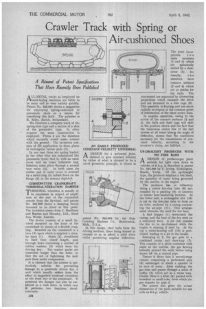
ALL-METAL tracks as employed on track-laying machines are liable to be noisy and to wear unduly quickly. Patent No, 543,041 shows a suggestion for employing spring-cushioned or pneumatic shoes as a means for remedying this fault. The patentee is K. Seiler, Zurich, Switzerland.
We illustrate a complete track of the spring-shoe type and a section of a shoe of the pneumatic type. In other respects the same construction is employed. Plates 4 are the members which normally would make contact with the ground. The invention consists of the application to these plates of rectangular rubber pads (1).
In one case these are spring loaded; in the other they are constructed like pneumatic tyres, that is, with an outer cover and an inner inflatable bag. Inflation takes place through a normal tyre valve (3). In both cases the rubber pad or outer cover is retained by a metal ring (5) bolted down on the flange (2) in the manner depicted.
CUSHION-TYPE CRANKSHAFT TORSIONAL-VIBRATION DAMPER
TORSIONAL vibration is usually at its .maximum in respect of amplitude at the end of the crankshaft remote from the flywheel, and patent No. 542,880 shows a damping device intended to he fitted at this point. The invention comes from C. Bradbury and Ruston and Hornsby, Ltd., Sheaf Iron Works, Lincoln.
The device consists of a small flywheel mounted on the front of the crankshaft by means of a flexible coupling. Mounted on the crankshaft is a boss (4) upon which is spigoted a circu lar mass (1). Studs (2), shouldered to limit their closed length, pass through holes containing a number of rubber washers (3) which form the driving key. The washer packs are somewhat longer than the holes, so that the act of tightening the nuts puts them under compression.
It is claimed that the scheme is particularly suitable for preventing damage to a positively driven fan, a unit which usually suffers from the effect of magnified torsional vibrations at the front end of the crankshaft. If preferred the damper can also be employed as a cush drive, in which case it performs two functions simultaneously. AN EASILY PRODUCED CONSTANT-VELOCITY UNIVERSAL
ADESIGN for a universal joint, claimed to give constant velocity by virtue of what is claimed to be a novel geometric principle, is shown in
patent No. 543,095 by the Gear Grinding Machine Co„ Hamtramck, Mich., U.S.A.
In this design, steel balls form the driving medium, these being housed in recesses so as to afford a solid drive whilst permitting angular deflection. The joint incor porates t w 0 main members (1 and 5) which are spherically united by a dustcover (3). In ternally, t h e members have concave surfaces (2 and 4) which act as guides for the balls, The last-named are separated by alternating projections which transmit the drive and are mounted in a free cage (6). This assembly is floating and can move radially in respect of the common point of intersection of the three centre lines.
In angular operation, owing to the action of the concave surfaces (2 and 4), the balls and their cage will shift to the position shown and the fact that the transverse centre line of the ball system at all times biseclis the angle of deflection, means that fhe conditions necessary for the transmission of constant velocity, according to the inventor's claim, are fulfilled.
UP-DRAUGHT PRODUCER WITH NO FIRE BARS
ADESIGN of producer-gas plant suitable for light vans down to vehicles of 8 h.p. is described in patent No. 542,906 by F. Irving, Kirklington, Beadle, Yorks. Of the up-draught type, the producer employs a wet blast, the quantity of water being governed by the suction of the engine.
The producer has as refractory lining a centre fire-clay tube (9) surrounded by a packing (8) of asbestos or similar heat-insulating material. At the lower end, a rectangular slot (10) is cut in the fire-clay tube to form an air inlet, enclosed by a casing containing the air-pipe (11). This arrangement obviates the need for fire bars.
A fuel hopper (1) surmounts the casing, and the base of the fire rests on a refractory floor. A lid (12) enables the fire to be de-clinkered while the engine is running if need be. At the top a water-heating coil (13) is positioned, leading to a jet in the intake.
Emerging at 2, the gas goes to a combined cooler and dust-trap (7). This consists of a plain container with water at the bottom, the gas flowing helically around the walls before being drawn off via a central pipe.
Thence it flows into a second-stage cleaner comprising a perforated pipe (6) submerged in about a quarter of an inch of water. After washing, the gas rises and passes through a series of baffles (5) which act as a water trap. Finally there is a filter (4) packed with horsehair or small coke, from which the gas departs by pipe 3.
The patent also gives the actual dimensions of the parts suitable for use with an 8 h.p.