


A SIXTY-CYLINDER ENGINE.
Page 22
If you've noticed an error in this article please click here to report it so we can fix it.
A Resume of Recently Published Patent Specifications. •
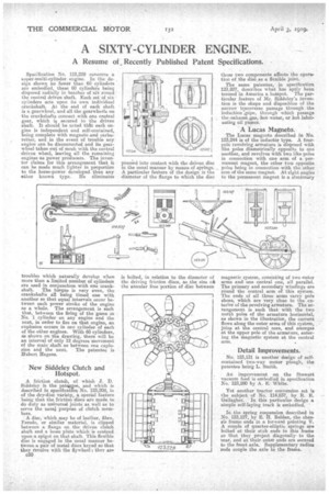
Specification No. 123,229 concerns a super-multi-cylinder engine. In the design shown no fewer than 60 cylinders are embodied, these 60 cylinders being disposed radially in batches of siX round the central driven shaft, Each set of six cylinders acts upon its own individual crankshaft. At the end of each shaft is a gearwheel, and all the gearwheels on the crankshafts connect with one central gear, which is secured to the driven shaft. It should be noted thgt each engine is independent and self-contained, being complete with magneto and carburetter, and in the event of trouble any engine can be disconnected and its gearwheel taken out of mesh with the central driven wheel, leaving all the remaining engines as power producers. The inventor claims for this arrangement that it can be made much lighter in proportion to the horse-power developed than any ether known type. He eliminates troubles which naturally develop when snore than a. limited number of cylinders are used in conjunction. with one crank shaft. The torque is very even, the crankshafts all being timed one with another so that equal intervals occur between each power stroke of the engine as a whole. The arrangement is such that, between the firing of the gases in No 1 cylinder on any engine and the next, in order to fire on that engine, an explosion occurs in one cylinder of each of the other engines. With 60 cylinders, lihown on the drawing, there will be an interval of only 12 degrees movement of the main shaftas between one explo sion and the next. The patentee is Hubert nagens.
New Siddeley Clutch and Hotspot.
A friction clutch, of which T. D. Siddeley is the patailtee, and which is described in specification No. 123,208, is of the dry-disc variety, a special feature being that the friction discs are made to do duty as universal joints as well as to serve the usual purpose of clutch members.
A disc, which may be of leather, Jibes, Ferado, or similar material, is clipped between a flange on the driven clutch shaft and a loose plate which is centred upon a spigot on that shaft. This flexible AIM is engaged in the usual manner beteen. a pair of metal discs keyed so that they revolve with the flywheel; they are
c50 pressed into contact with the driven disc in the usual manner by means of springs. A particular feature of the design is the diameter of the flange to which the disc is bolted, in relation to the diameter of the driving friction discs, as the size oft the annular free portion of disc between those two components affects the operation of the disc as a flexible joint.
The same patentee, in specification 123,207, describes what has aptly been termed in America a hotepot. The par-. ticular feature of Mr. Siddeley's invention is the shape and disposition of the narrow transverse passage through the induction (pipe, through which passage the eahaust.gas, hot water, or hot lubricating oil passes.
A Lucas Magneto.
The Lucas magneto described in No. 123,244 is of the inductor type. A fourpole revolving armature is disposed with
123207 like poles diametrically opposite to dne another, and revolves with two like poles in connection with one arm of a permanent magnet, the other two opposite poles being in connection with the other arm of the same magnet. At right angles to the permanent magnet is a stationary magnetic system, consisting of two outer arms and one central one, all parallel. The primary and secondary windings are round the central arm of this system. The ends of all three arms carry pole shoes, which are very close to the exterior of the revolving armature. The arrangement is such that with the two north poles of the armature horizontal, as shown in the illustration, the current flows along the outer arms of this system, joins at the central core, and emerges at the upper pole of the armature, entering the magnetic system at the central arm.
Detail Improvements. .
No. 123,131 is another design of selfcontained two-way motor plough, the patentee being L. Smith.
An improvement on the Stewart vacuum feed is embodied in specification No. 123,280 by A, E. White.
Yet another tractor conversion set is the subject of No. 114,837, by R. E. Gallagher. In this particular design a simple self-laying track is embodied.
In the spring suspension described in No. 123,127, by E. II. Belden, the chassis frame. ends in a forward pointing V. A couple of quarter-elliptic springs are bolted at their stub ends to this fraine so that they project diagonally to the rear, and at their outer ends are secured to the front axle. Supplementary radius rods couple the axle to the frame.