


SOME CHANGE-SPEED GEARS.
Page 42
If you've noticed an error in this article please click here to report it so we can fix it.
A Résumé of Recently Published Patents.
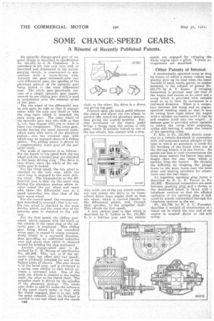
An epinyclic change-speed gear of unusual.dcLign is described in specification No. 161,613, by J. H. ChaMberS. It is embodied in the rear axle case, and, as described and illustrated in the accompanying sketch, is constructed in conjunction with. a worm-driven axle. Actually the gear ' surrounds -40e rear axle differential gear, the spindles of the planetary pinions of the epicyclic gear being bolted to the main differential • ease. The whole gear :practically consists of a simple epicyclic gear supplemented by one sliding gear which is used in conjunction with the external wheel of this gear.
The sun wheel of the differential may he slid upon its axle so that it engages either with the axle case itself or with the ring upon which is mounted the main worm gear. The outer wheel of :the epicyclic gear may also slide so that it, too, may engage with one or other, of these two components. This outer gear, besides having .the usual internal teeth, which mesh with those of the planetary pinions, also has external cogs with which may be engaged those, of a sliding pinion. The sliding pinion is driven by a supplementary worm -gear off the propeller shaft..: The mode of operation is as follows : For, the fourth or top speed both the sun wheel and the external gearare clutched to the main driving. ring. The drive is then direct, since the whole of the epi
cyclic gear is locked. .
For the thirdspeed, the sun wheel is clutched to the axle case, while the outer ring is engaged to the main' driving wheel. The transmission to the differential case is thus via the outer ring driving the planetary pinions which revolve round the sun wheel and carry with them the differential case at a speed somewhat' lees than that of the main worm wheel.
For the second speed, the arrangement just described is reversed that IR to say, the sun wheel is clutched to the main 2 driving wheel, and the outer ring of the epicyclic gear is clutched to the axle case.
For the first speed, the sliding gearwheel, which engages with the teeth on the outside of the outer ring of the sini cyclic gear, is employed. This sliding gear being driven by the secondary tvorm gear, is caused to rotate comparatively slowly in a rearward direction, thus providing an additional reduction over and above that which .is obtained merely by holding the ring stationary.
Another change-speed gear is described by C. H. Strong in specification No. 161,649. This, too, is of .the epicyclic type, lffit offers only two speeds, and is evidently intended for one of the lighter types of chassis. The gear shown is of the bevel type, and is contained in a casing very similar to that which encloses a'universal joint. One of the main sun wheels is coupled to the engine shaft, the other to the clutch shaft. The propeller shaft is. driven by the spindles of the planetary pinions. The whole year slides to and fro under the influence of the usual clutch pedal. so that, with The clutch engaged, that is to say, with the pedal released, since the flywheel is counled to one sun wheel and the clutch
shaft to the other, the drive is a direct one giving top gear. Pressure upon the clutch pedal releases the.clutch and allowa.the sun wheels to revolve idly rotind the planetary pinions, thus giving the neutral position. Further movement of the clutch pedal brings a flange upon the casing of this gear, which is actuallybolted to one of the sun wheels, into contact with a stop.
This holds one of the sun wheels stationary and causes the drive to be transmitted direct from engine shaft to that sun wheel, which is carried, thereby to the differential pinion, and, through their spindles, to the propeller shaft.This affords the first speed. A very curious gear is that which is described by T. Lafitte in NO. 151,283. It is a. friction, gear and the various
speeds are engaged by Swinging the whole engine upon a pivot. Various arrangements are described.
Other Patents of Interest.
A mechanically operated scoop or drag by means of which a motor vehicle may quickly pick up its load when the latter consists of Sand, earth, gravel, or similar material, is the subject of -patent No. 161,771 by A. V. biake. A swinging framework is pivoted near the rear of the wagon and carries at its outer end a scoop which is provided with suitable stops so as to limit its movement in a rearward direction. There is a connection between the scoop and an engineoperated winding drum. to that it may beswung 'from right below the wagon with a circular nnSvenient until it tips up and empties. itself into the wagon. A balance gear is provided which operates to return the scoop after emptying, whilst still-leaving it under the 'control of the operating cable. F. Kec, in No. 131,003, directs attest-tion to a certain drawback in connection with self-contained. motor ploughs of the type in which no provisionis Made for the levelling of the frame when one of the driving wheels is in the iiirroW. lie points out that in such circumstances the front shear nearest the furrow Cuts more deeply thanthe rear -shear which is farthest from the furrosv-. -He obviates the difficulty by hingeing the plough -frame to the main frame near the front shear and making -provision for adjustntent near the rear: shear.
An ingenious sparking plug tester is described by F. L. F. Vaivel in No. 161,852. Electrical connections are math between sparking plug anda device or the .dashboard which it fitted with a telephone receiver So that the efficient operation of the sparking plug is Indicated by sounds transmitted through this telephone receiver to the ear. No, 161,74g, by II. J: C. Forrester; 'describes a method of construction of -a steam car in which the rear end of ths engine is coupled direct to the axis casing.