


HINTS ON MAINTENANCE.
Page 28
If you've noticed an error in this article please click here to report it so we can fix it.
How to Get the Best Out of a Vehicle, to Secure Reliability and to Avoid Trouble.
CONTRIBUTIONS are invited for this page from 'fleet managers, drivers, garage foremen, and mechanics, works staff and draughtsmen, and will be paid for on a generous scale. Every system, make, and type of commercial motor vehicle is being dealt with, and the matter should be written with a view to the disclosure of workshop and garage practice in the maintenance of a vehicle.
407.—Dismantling and Repairing the Small-end of the Foden Connecting Rod.
In removing the brasses of the small end of the connecting rod on the Foden steam wagon, great care must be taken to avoid damaging them. They are marked " R " and L" respectively, and the housing is marked in the same way, to show how the brasses must-be Withdrawn. The half-moon brass is held in the housing by a lug which protrudes through a hole in the connecting rod.
To remove these brasses, a g-in. steel peg can be employed, this being held against the lug a the halfmoon brass and a sharp blow being given to it by means of a hammer.
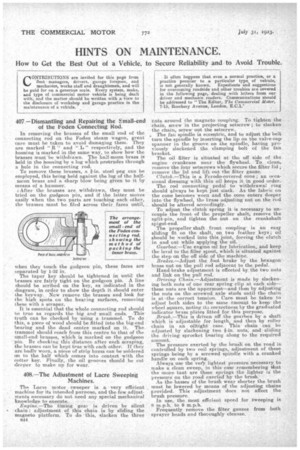
After the brasses are_ withdrawn, they must be tried on the gudgeon pin, and if the latter mows easily when the two parts are touching each other, the brasses must be filed across their. faces until,
when they touch the gudgeon pin, these faces are separated by 1-32 in.
The taper key should be tightened in until the brasses are fairly tight on the gudgeon pin. A line should be scribed on the key, as indicated in the diagram, in order to show the depth it should enter the keyway. New remove the brasses and look for the high spots on the bearing surfaces, removing These with a scraper. It is essential that the whole connecting rod should ne true as regards the big and small ends. -Thistruth can be checked by using a trammel. To do this, a piece of wood should be fitted into the big-end hearing and the dead centre marked on it. The trammel should reach from this centre to that of the small-endbrasses, which is marked on the gudgeon • pm. By checking this distance after each scraping, the brasses can be kept true with each other. If they. are badly worn, a niece of strip brass can be soldered on to the half which comes into contact with the cotter key. Finally, the oil grooves should be cut
deeper to make up for wear.
408.--The Adjustment of Lacre Sweeping Machines.
The LaCie motor sweeper is a very efficient _ machine for its intended purpose, and the few adjustments necessary do not need any special mechanical knowledge to execute.. . .
Engine.—The timing .geaf is driven by silent • -chain ; adjustment of this chain is by sliding the magneto platform. To do -this, slacken the three n44
nuts around the magneto coupling. To tighten the chain, set ew in the projecting setscrew ; to slacken the chain, screw out the setscrew.
. The fan spindle is eccentric, and to adjust the belt turn the spindle by inserting the lip on the valve-cap spanner in the groove on the spindle, having previously slackened the clamping bolt of the fan bracket.
The oil filter is situated at the off side of the engine crankcase near the flywheel. To clean, remove-the four setscrews which secure the filter lid ; remove the lid and lift out the filter gauze. Clutch..--This is a Fcrodo-covered cone ; an occasional dressing with thin oil keeps it in good order. The rod connecting pedal to withdrawal ring should lw-ays be kept just -stack. As the fabric on the cone becomes worn and the cone enters deeper into the flywheel, the brass adjusting nut on the rod should be altered a.ecoidingly.
To adjust the clutch spring it is necessary to uncouple the front of the propeller shaft, remove the split-pin, and tighten the nut on the crankshaft spigot-end.
The propeller shaft front coupling is an . easy sliding fit on the shaft, on two feather keys ; oil should be worked into this joint, forcing the clutch in and out while applying the oil.
Gearbox.—Use engine oil for lubrication, and keep the level to the filler spout, which is situated against the step on the off side of the machine. Brakes.—Mjust the foot brake by the hexagon brass nut on the pull rod adjacent to the pedal.
Hand-brake adjustment is effected by the two nuts and link on the pull rod.
Driving Chain.—Adjustment is made by slacken-' Mg both nuts of one rear spring clip at each side— these nuts are the uppermost—and then by adjusting the nuts on the-screwed axle studs until the chain. is at the correct tension. Care,. must be taken to adjust both sides to the same amount to keep the wheel square, noting its correctness by the graduated indicator brass plates fitted for this purpose. Brush.—This is driven off the gearbox by a shaft which is adjustable for length, and then by roller chain in an oiltight ease. This chain can be adjusted by slackening two g-in. nuts, and sliding the driving sprocket bearing along to the required amount.
The pressure exerted by the brush. on the road is controlled by two coil springs, adjustment of these springs being by a screwed spindle with a cranked handle on each spring. Always use the very lightest pressure necessary, to make a clean sweep, in this ease remembering that the more taut are these springs the lighter ii the pressure on the road exerted by the brush. As the basses of the brush wear shorter the brush must be lowered by means of the adjusting chains provided. This adjustment does not affect the brush pressure.. In use, the most efficient speed for sweeping is 8 mph. to 9 m.p.h. Frequently remove the filter gauzes from both sprayer heads and thoroughly cleanse.