


ELECTRIC BRAKING
Page 42
Page 43
If you've noticed an error in this article please click here to report it so we can fix it.
on the Modern Trolleybus
BRAKE wear on motorbuses and trolleybuses presents no easy problem to thoseresponsible for maintenance. In the case of motorbuses, it has been tackled by succeeding improvements in brake-drum design, particularly in respect of the metal employed, and in the use of the right type of facing material.
With trolleybuses, a more direct solution has been found, whereby the use of the wheel brakes is virtually confined to bringing the vehicle to rest from a moderate road speed, and holding it stationary at service stops. This need is met by controlled rheostatic braking, retardation being effected through the transmission via the traction motor, which, on the overrun of the vehicle, reverses its function and acts as a generator.
When the power-weight ratio of trolleybuses was low, and performance schedules were below present standards, normal wheel braking met the requirements, but with the demand for larger vehicles and better service performance, traction motors of increased power were called for, with the corresponding need for greater brake efficiency. To increase drum diameter meant using a larger wheel, and this was not considered expedient, as it also involved raising the floor level. As there was thus a definite limiting factor in the frictional area that could be introduced in the drum brakes, attention was devoted to electric braking.
Simple, But Limited in Capacity
An eddy-current brake, on an extension of the motor shaft, was used in a number of instances, but whilst it was commendable in its simplicity of operation and ease of maintenance, it was somewhat limited in capacity. The alternative method was to use the motor as a generator, which was arranged to produce a retarding effort, the current either being returned to the line, or diverted to a local circuit formed by a normal starting resistance.
One of the first electric braking systems evolved was of the regenerative type, so called because energy was returned to the line during braking, using a compoundwound motor. With the early. regenerative systems it is not clear, however, whether the intention was to save electricity or to reduce wear and tear of the mechanical brakes by relieving them of much of their duty.
Alternative schemes of rheostatic braking were developed, in which a, series-wound motor was employed, and energy was not returned to the line, The claims made for the system were that of simplicity and that the motor, of similar weight to a compoundwound machine, could, because of its superior field-coil spate factor, provide a given acceleration with a smaller starting current, so that the energy consumption was no greater than when a saving was effected by employing a regenerative system.
One rheostatic system, with series-wound motor, employed a braking resistance regulated by a centrifugal switch. The advantage of the compound-wound
motor system was that, by opposing the series and shunt field-coils during braking, the braking effort reached a maximum value, which could not, in any Circumstances, . be extended.
This system was thus foolproof, and the danger of overstressing the transmission during braking was removed. With rheostatic braking systems, using a series-wound motor and resistance values giving reasonable rates of retardation at the normal operating speeds, there was a danger of the driver applying the brake too fiercely when the vehicle was travelling at high speed. This. meant possible damage to the transmission, besides producing severe electrical conditions likely to cause flashover and consequent damage to the motor.
Although the rheostatic brake was used on trams before being applied to trolleybuses, there was no need to take precautions against fierce operation because the low coefficient of friction between the steel wheels and the rails—about 0.25—permitted slip to tate place t' provide stress relief. In the case of a rubber tyre on a macadam road surface, with -a coefficient of friction up to 1.0, there is little or no relief to severe braking, so that the stresses have to be absorbed in the transmission.
It was because of the inherent disadvantages of the series-motor rheostatic system of braking that the compound-wound-motor regenerative method saw increasing use. Many problems had to be solved, however, before the system could be made to operate with complete satisfaction. With present-day conditions of power supply, regenerative systems, whereby the current is returned to the line, possess certain disadvantages, and operating experience has shown that with the schedule speeds now obtaining, it is more important to develop braking systems that will relieve the brake drums and facings of wear, than to attempt to save energy by returning current to the line.
The latest developments, therefore, tend towards the adoption of compound-motor rheoStatic systems using a stabilizing resiitance, by means of which the variations in armature current stabilize the braking torque by imposing a correcting voltage in the shunt field winding. In a system in which there is a connection between the power-supply circuits and the armature there is, when using a rheostatic brake, the possibility of a fault establishing motoring conditions liable to produce serious consequences.
Crompton Parkinson, Ltd., a concern responsible for the trolleybus equipment bearing its name, has overcome this disadvantage by an alternative arrangement, which is a development of what is termed controlled rheostatic braking.
The scheme includes a compound-wound motor with a comparatively large series winding to give a high torque for starting. Thus, an outstanding advantage of the series-motor system is retained without the disadvantage that it is not practicable to provide efficient braking which can be controlled to limit the maximum braking effort to a definite value, and so prevent damage and excessive wear in back-axle components.
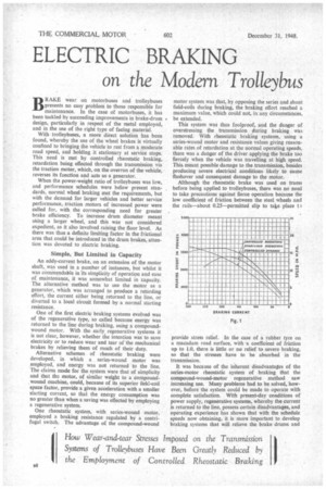
An Approximation to the Ideal The ideal braking system would be one giving a constant degree of retardation from maximum speed to a state of rest, but although such a system cannot be realized in practice, a near approximation can be obtained with equipment which provides such a condition down to a speed of 8 m.p.h. or less. This characteristic is the outstanding feature of the Crompton Parkinson control scheme, in which the series field winding i used as a decomponnding winding during braking.
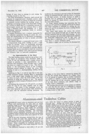
Referring to Fig. 1, it will be seen that in the controlled theostatic system, braking effort is maintained over a wide speed range, bringing the vehicle down to about 31 m.p.h., when the drum, brakes come into operation to bring the machine to rest. The general arrangement of the Crompton Parkinson circuit is shown in Fig. 2.
On starting, the contactors SI, LP and LN, are closed, whilst FL and F2 are open, together with all other contactors. The motor is thus connected across the line—with full-series and part-shunt field excitations— in series with the maximum starting resistance. To accelerate, the resistance is cut out in steps, by sequential closing of contactors RI-R5, until the motor is running on full field current. A further increase in speed is obtained, first by reduction of the field current, and finally by closing F2, which diverts a greater part of the series field current.
To bring electric braking into operation, the line contactors LP and LN are opened, and B and FLelosed. Full shunt excitation is obtained by closing the contactors SI and 52, to connect the shunt winding directly across the line.
This shunt field excites the motor, the current generated being passed through part of both the main starting resistance and the series field winding. As this current increases, the series-field ampere-turns opposite the shunt-field ampere-turns and, in this way, the braking effort is stabilized, that is, retardation is constant above a certain minimum speed.
To obtain a higher rate of braking, the decompound
ing effect of the series field is reduced by closing F2, so that the current then balances at a higher value. It is of interest to mention that no, further resistances are needed to control a normal series-wound motor, and by making use of the two-point tapping system of the field divert resistance, and infinite range of braking values is obtainable.
The braking characteristics of the system, as outlined, are such that the rear axle of a trolleybus is relieved of considerable wear-and-tear stresses when the vehicle is being braked at high speed.