


How to Keep Your Lorry Fit.-111.
Page 5
Page 6
Page 7
If you've noticed an error in this article please click here to report it so we can fix it.
We Deal this Week with the Leyland Chassis. The Special Instructions for this, Additional to those of Our Introductory Article of the 10th inst., are Few; they Refer Principally to Lubrication.
Leyland petrol wagons are made in various sizes, the capacities ranging from one to six tons inclusive. The instructions for the care of Leyland chassis which we give below, careful attention to which will ensure
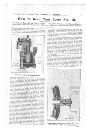
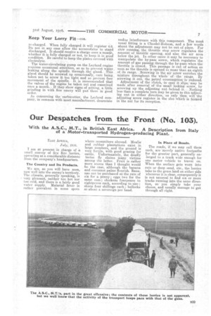
fitness of the vehicle, are so written as to apply to all models. The detailed illustrations of vehicle pasts refer in particular to the War Department subsidy model, a very popular one amongst all classes of user. All models of the Leyland chassis are similarly designed, and incorporate four-cylinder engines, three or four-speed gearboxes with gate type of selector gear and live axle. In the ease of the latter units, except for one or two models, double reduction gear is the final means of transmission. In this particular form of construction the Leyland company, if not the actual pioneers, may claim to be the most experienced. It is probable that the success of this type of final drive as exemplified on the company's chassis -weighed considerably with the War Office when drawing up the existing subsidy specification, which requires a live. axle embodying a bevel, drive. In the building of commercial vehicles, once the original question of design has been settled, and the strength of the various parts suitably proportioned to the loads,. further improvements are alOng the lines of rendering the chassis what is termed fool-proof. Hy this is meant, as a rule, so arranging the control of the chassis and the parts which require attention, that the least intelligent driver is not likely to make an error serious enough to cause harm to the vehicle. Other things being equal, it is only likely that we shall find that the productions of a firm of longest standing shall have most, nearly approached perfection in this respect. The Leyland company is one of the oldest heavy-vehicle manufacturmg,concerns., and moreover it has paid particular attention to this department of design, and, consequently', as might be expected, the amount of attention which a Leyland chassis needs at the hands of a driver is very small indeed. A casual glance through a Leyland instruc
tion book reveals, that quite half of this small but informative volume is devoted to one subject—that of lubrication. It would almost appear that all that is left for the driver to do on a Leyland chassis to keep it in good order is to lubricate the moving parts as occasion requires.
A discussion of the lubrication of a commercial vehicle may suitably be divided into two parts ; one dealing with the engine, the other with the transmission. As concerning the former, on the Leyland chassis oiling of the engine is effected by means of a gear oil-pump underneath the 0i1 .sump of the crankcase. The position of this is shown quite clearly in our illustration of the Leyland engine. This pump delivers oil through passages in the crankcase to the .three main bearings, thence the oil travels through drilled holes in the crankshaft to the connecting rod big-ends. 'All the other moving parts within the crankcase are lubricated by spray thrown off from the revolving shaft. An additional pump serves merely, to circulate the oil past an indicator or tell-tale on the dashboard. -As this second pump takes oil from a higher level in the sump than the main pump, it therefore ceases to operate this tell-tale whilst there is still oil left in the crankcase from which the main pump may draw. The warning that the oilis getting. low is given to the driver while there is still sufficient oil available for running approximately a further 20 miles. In order to regulate the actual oil pressure to the main bearings, a pressure-regulating valve is fitted in the Main: oil passage between the pump and. the bearings. It is possible to regulate this valve whilst the engine is running. The pressure gauge serves to show the pressure of oil. The company recommends ULM', this be kent at ribmit 10 lb. per sq. in. Before reaching the suction side of the pump, tl the oil must
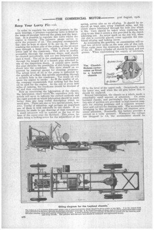
i pass through a large sieve,. which s placed in. the lower half of the crankcase. This • sieve is readily accessible through the crankcase doors, and should be cleaned periodically, and not less frequently than once a. week. The oil in the crankcase is replenished through the hinged lid of a branch pipe attached to one of the inspection doors. A conical sieve inside this pipe obviates the possibility of dirt being poured direct into the crankcase. This sieve should on no account be removed except for cleaning purposes. The actual level of ail in the sump is indicated by the spindle of a float, this spindle protruding through a suitable hole in the crankcase. Too much oil will cause the engine to smoke, As t..13 the quality of oil, the company recommends that nothing but the best oil be used for the engine. At the end of every 2000 miles of running, the crankcase should be drained of oil and then replenished. Now as concerning the hiprication of the chassis, the lubrication chart' which 16e reproduce with this article will serve to indicate the correct methods and the right periods at which lubrication should be made better than any long verbal description which we could give. . There are one or two special points, however, worthy of attention, and perhaps an important one of these is with referente to the clutch. If reference be niade to our drawing of that component, a small set-screw will be noticed on the top of the boss of the cover over the flywheel. This screw, besides being a• locking-screw for the adjustMent of the spring, serves also as an oil-plug. It should be removed at least once every hundred miles, and the clutch sleeve lubricated through the hole into which it fits. Care should be taken when replacing this plug to see that it enters a slot provided in the clutch adjusting nut. An arrow mark on the nut will, when the slot is correctly placed, come opposite the combined oil-plug and locking screw. As concerning the gearbox, an examination will reveal two oil-level cocks on the near side of this unit. These cocks show the minimum and maximum levels of the oil. Heavy cylinder oil should be used, and not grease. When replenishing• the supply of lubricant, fill to the level of the upper cock. Occasionally open the lower one, and when the oil gets below this, it should be replaced.
Beyond lubrication, the chassis as a whole needs a remarkably small amount of attention. On some Leyland chassis, and particularly the heavier ones, two sets of ignition are provided—a, high-tension magneto for running purposes and a separate accumulator and coil set for starting only. The accumulator belonging to this second ignition set requires. occasional. attention. Nominally, this battery provides a current at 4 volts pressure. Whenever the voltage has dropped to 3.6, the accumulator should be
re-charged. When fully charged it will register 4.6. . Do not in any case allow the accumutator to stand discharged. It should receive a charge once a month,. whether it is fully charged or not, to keep it in good condition. Be careful to keep the plates covered with electrolyte.
The water-circulating pump on the Leyland engine requires occasional attention, so as to prevent water. leaking along the spindle through _the gland. This gland should be screwed up. occasionally, care being taken not to screw it too tight and so prevent free movement of the spindle. It is recommended that the valves of the engine be taken out and examined once a month. If they show signs of pitting, a little grinding in with fine emery will put them in good order.
As concerning the carburetter, the Leyland company, in common with most manufacturers, deprecate undue interference with this component. The most usual fitting is a Claudel-Hobson, and a few words about the adjustment may not be out of place. For slow running, the throttle stop screw regulates the amount of throttle opening, and also the air area below the jet. In other cases it may be necessary to manipulate the by-pass screw, which regulates the amount of gas passing through the by-pass-when the throttle is closed. This passage is out of action as soon as the throttle is opened to more than an eighth of its range. ..Screwing in the air screw enriches the mixture throughout the -whole of the range. By screwing it out, the petrol consumption is. reduced.
Adjustment of the clutch, -in case it slips; may be made after removal of the small lockingscrew, by screwing up the Adjusting nut behind it. Nothing less than a complete turn may be given to this adjusting nut in either direction, as only then will 'the adjusting screw register in the slot:which-is formed in the nut for its reception.