


An Automatic Overload Release
Page 64
If you've noticed an error in this article please click here to report it so we can fix it.
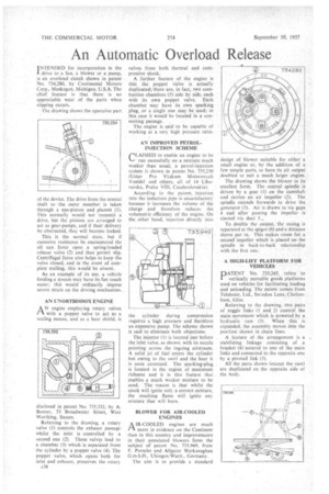
INTENDED for incorporation in the drive to a fan, a blower or a pump, is an overload clutch shown in patent No. 734,280, by Continental Motors Corp., Muskegon, Michigan, U.S.A. The chief feature is that there is no appreciable wear of the parts when slipping occurs.
The drawing shows the operative part of the device. The drive from the central shaft to the outer member is taken through a sun-pinion and planets (1). This normally would not transmit a drive, but the pinions are arranged to act as gear-pumps, and if their delivery be obstructed, they will becomelocked.
This is the normal state, but if excessive resistance be encountered the oil can force open a spring-loaded release valve (2) and thus permit slip. Centrifugal force also helps to keep the valve closed, and in the event of complete stalling, this would be absent.
As an example of its use, a vehicle fording a stream may have its fan touch water; this would ordinarily impose severe strain on the driving mechanism.
AN UNORTHODOX ENGINE
A N engine employing rotary valves with a poppet valve to act as a scaling means, and as a heat shield, is
disclosed in patent No. 735,332, by A. Rooter, 53 13roadwater Street, West Worthing, Sussex.
Referring to the drawing, a rotary valve (1) controls the exhaust passage whilst the inlet is controlled by a second one (2). These valves lead to a chamber (3) which is separated from the cylinder by a poppet valve (4). The poppet valve, Which opens both for inlet and exhaust, preserves the rotary
A38 valves from both thermal and compressive shock.
A further feature of the engine is that the poppet valve is actually duplicated;:there are, in fact, two combustion chambers .(5) side by side, each with its own poppet valve. Each chamber may have its own sparking plug, or a single one may be used; in this case it would be located in a connecting passage.
The engine is said to be capable of working at a very high pressure ratio.
AN IMPROVED PETROLINJECTION SCHEME ("LAIMED to enable an engine to be
run sucessfully on a mixture much Weaker than usual, a petrol-injection system is shown in patent No. 735,230 (Ustav Pro Vyzkurn Motorovych Vozidel and others, all of 14 Lihovarska, Praha VIII, Czechoslovakia).
According to the patent, injection into the induction pipe is unsatisfactory because it increases the volume of the charge and therefore reduces the volumetric. efficiency of the engine. On the other hand, injection directly into
the cylinder during compression requires a high pressure and therefore an expensive pump. The scheme shown is said to eliminate both objections.
The injector (I) is located just before the inlet valve, as shown, with its nozzle pointing across the ingoing airstream. A solid jet of fuel enters the cylinder but owing to the swirl and the heat it is soon atomized. The sparking-plug is located in the region of maximum richness and it is this feature that enables a much weaker mixture to be used. The reason is that whilst the spark will ignite only a correct mixture, the resulting flame will ignite any mixture that will burn.
BLOWER FOR AIR-COOLED ENGINES
A1R-COOLED engines are much more in evidence on the Continent than in this country and improvements in their associated blowers form the subject of patent No. 733.949, from F. Porsche and Allgaier Werkzeugbau G.m.b.H.. Uhingen/Wurtt., Germany.
The aim is to provide a standard design of blower suitable for either a small engine or, by the addition of a few simple parts, to have its air output doubled to suit a. much larger engine.
The drawing shows the blower in its smallest form. The central spindle is driven by a gear (1) on the camshaft and carries an air impeller (2). The spindle extends forwards to drive the generator (3). Air is drawn in via gaps 4 ad after passing the impeller is ejected via duct 5.,
To double the output, the casing is separated at the spigot (6) and a distance sleeve put in. This makes room for a second impeller which is placed on the spindle in back-to-hack relationship with the first one.
A HIGH-LIFT PLATFORM FOR VEHICLES
pATENT No. 735,245, refers to vertically movable goods platforms used on vehicles for facilitating loading and unloading. The patent comes from Telehoist, Ltd., Swindon Lane, Cheltenham, Glos.
Referring to the drawing, two pairs of toggle links (I and 2) control the main movement which is powered by a hydraulic ram (3). When this is expanded, the assembly moves into the position shown in chain lines.
A feature of the arrangement is a stabilizing linkage consisting of a bracket (4) secured to one of the main links and connected to the opposite one by a pivoted link (5).
All the parts shown (except the ram) are duplicated on the opposite side of the body,