


Patents Completed.
Page 22
If you've noticed an error in this article please click here to report it so we can fix it.
Complete specifications of the following patents will be sent to any address in the United Kingdom upon receipt of eightpence per copy at the Sale Branch, Patent Office, Holborn,
CARBURETTER. — Walker a u d Another. — No. 17,490, dated 20th August, 1908.—The carberetting chamber is open at its underside, and the fuel nozzle projects a certain distance into the chamber. Surrounding the fuel nozzle, is the usual choke-tube, which has one or more openings at ite upper end communicating with the carburetting chamber. The choke-tube is made
integral with a sliding sleeve that fits the lower end of the carburetting chamber, and this sleeve has a number of triangular holes or ports formed in the walls thereof. The top of the choke-tube is closed and is connected by means of a suitable spindle with a dash-pot arranged above the carbliretting chamber. The object of the dashpot is to steady that movement of the choke-tube and its sleeve which is caused by the variable suction of the engine, and in -order to assist still further in regulatIng this movement a spiral spring is interposed between the choke-tube arid the top of the carburetting chamber. It will be Rem that, when the speed of the engine increases, the choke-tube, together with its sleeve, will he moved upwardly and will thus uncover the triangular holes cr parts in the sleeve, so that an auxiliary supply of air will be admitted to the carburetting, chamber.
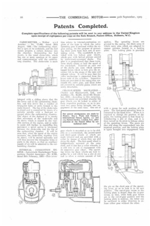
INTERNAL COMBUSTION ENGINE.—Industrieele Maatsehappy Trornpenhurg (Sociiite Anonyme).—No. 4,789, dated 26th February, 1909.—This inven
tion relates to internal-combustion engines of the type in which the valveoperating gear is enclosed within the engine easing, for the purpose of protecting these parts from dust and of minimising noise. The crankshaft is provided with two helical gear wheels, which gear with helical pinions carried
by transversely-arranged shafts. The gear is so proportioned that these transverse shafts rotate at half the speed of the crankshaft, Mounted on each end of the shafts are cams which operate tappet levers which in turn give the necessary lift to the stems of the inlet and exhaust valves. It will be seen that the valve mechanism is supported from the hewer ends of the cylinders. Inspection holes are provided in the casing that surrounds the valve gear, and these holes are covered by suitable plates which are easily detachable.
CHANGE-SPEED MECHANISM— Clayton and Shuttleworth, Ltd., and Another.—No. 26,691, dated 9th December, 1908.—According to this invention, locking means are provided whereby the gear wheels can he locked in either of their respective positions, so as to prevent two gears being brought into engagement at the same time. One set of
gear wheels is mounted so as to be slidable on a countershaft, the second-speed and third-speed wheels of which are made integrii and are provided with a collar by means of which they are slid along the shaft. The first-speed wheel is independently mounted on the same shaft, and it also has a collar whereby it is slid into or out of engagement with its respective gear wheel. The operating levers for these wheels are tied together by a rod which has a slot at one end to allow a certain amount of lost
motion. The operating levers are pivoted to the easing, the short arms of which carry pins which are adapted to engage recesses formed in a locking plate. This lockmg plate is provided
with a recess for each position of the gears. The first-speed-operating lever is connected to the hand lever. When it is required to change the position of the gears, the locking plate is first freed by withdrawing a pin or stop, and it is then turned on its pivot to release either of the operating levers. The gears are then slid along the countershaft into the required position, and the locking plate is again brought into engagement with
the pin on the short arm of the operating lever, so as to lock it in its new position. The out-of-gear recess in the. locking plate is deeper than the in-gear recess, so that, when both gear levers are in the out-of-gear position and the locking plate is midway, the latter cats be oscillated in either direction to release either gear without the other.