


Interesting Features in
Page 46
If you've noticed an error in this article please click here to report it so we can fix it.
New Trolleybus Boom Gear
rrliE fundamental advantage of the I trolleybus over the tram, namely, its freedom of course, is largely responsible for a difficulty. that is of less moment irt the case of the latter vehicle, i.e., the possibility of the boom leaving the overhead conductor is greater. Apart from the inconvenience of this occurrence, there is also the risk of the boom becoming caught up on a cross cable, which may damage a standard, or of breaking the windows of adjacent buildings.
In a recently patented invention of Mr. M. Aymard, 72, Highdown Road, Hove, the prevention of such mishaps has received close attention. The trolleybus-boom mechanism he has evolved is so designed that, among a .number of other desirable features, the boom drops and is automatically locked against motion about its vertical pivot so soon as the trolley wheel is relieved of the downward pressure of the conductor.
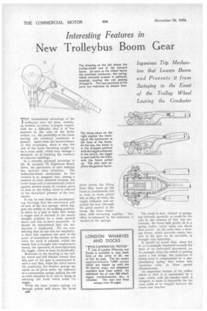
It can be seen from the accompanying drawings that the reactionary pull of each of the two springs, which support the trolley in its working position, is taken by a pair of links that forms a toggle and is retained in the nearly straight position by a hook pivoted above and free to move rearwards. It should be remembered that the mechanism is duplicated. We are considering that on one side for simplicity. A third link regulates the path of the point of attachment of the tension rod when the hock is released, whilst the fourth link is brought into employment during the operation of restraightening the toggle, which is done hydraulically.
Reference to the drawing of the trolley wheel and bell bracket reveals that this part of the gear is constructed in such a way that, when the wheel leaves the conductor, the bracket springs upwards on its pivot under the influence of a compression spring, pulling the rod or cable attached to it, and in doing so releasing the hook which holds the toggle.
While the main tension springs act through points well above the bo3m n28
pivot centre, the lifting force they exert on the boom is considerable, but so soon as these points fall, as they do when the toggle collapses, and approach the axis (through the pivot centre) of the boom, the force dimin ishes with increasing rapidity. This effect is enhanced by the reduction cf tension in the springs. The result is that, instead of springing violently upwards, as would be the case in the absence of this trip mechanism, the boom falls gently onto a spring buffer, which takes any shock that occurs. At the same time, a locking device, which prevents rotary motion of the gear on its turntable, is brought into operation.
It should be noted that, when the bc m is normally depressed towards the limit of its downward movement, as, for example, when the vehicle is passing under a low bridge, the reduction in lifting force is compensated by a supplementary spring that comes into operation only in these special circumstances.
An important feature of the trolley wheel is that it is surrounded by a cage, which, with the bracket itself, is designed to make it impossible for the cross cable to be trapped between the wheel and bracket.