


Improved Fixing Methods for Cylinder Liners
Page 48
If you've noticed an error in this article please click here to report it so we can fix it.
A R8sumi of Recently Published Patent Specifications
DATENT No. 406,000, by C. A. Vii1 hers, 48, Albemarle Street, London,' W.1, and E. F. Simmons, "Brackendale," Charteridge Road, Chesham, Bucks, shows a method of holding cylinder liners in position, by which, it is claimed, an improved joint is made between the liner and the cylinder head.
The drawing shows an assembly of liner (4), cylinder (2), and cylinder head (1). The interesting point to note is that the gasket (5) is not sandwiched in the ordinary manner, but is compressed to a certain thickness after which the head and liner themselves meet, at the point 3. To ensure the success of this method, the gasket must possess con. sklerable elasticity, and this is provided for by constructing it in the form of a metal bellows. A similar seal (with the addition of a rubber ring) is provided at the lower end of the cylinder.
Further advantages are claimed in respect of improved cooling, the combustion chamber being adequately surrounded by water, whilst the gasket is actually in contact therewith.
Improvements in Clutch-operating Gear.
EASE of assembly is the advantage claimed in patent No. 406,143 by Daimler-Benz A.G., Stuttgart-Unterttirkheim, Germany.% The novel point of this invention is the position of the clutch fork pivot; this is vertical
instead of horizontal, which is more usual.
Referring to the drawing, 2 is the clutch fork, pivoted about a vertical spindle (1). Beyond the pivot an arm (3) extends into the path of the pedal arm (4) to which it is secured by a bolt having ball-and-socket ends. Accessibility and simple assembly are assured, it is claimed, owing to the absence of a cross-shaft, which permits the unit to be inserted from the side. s42 Independent Wheel Springing.
F:URTHER developments in independent suspension systems are disclosed by J. Ganz, 85, Zeppelinallee, Frankfurt, Germany, in specification 406,156. According to the inventor, systems in which the road wheels are maintained in a vertical position irrespective of the spring position are less self-damping than the systems in which the road wheels may be angularly deflected. In the latter case, the deformation of the tyre, it is slated, acts as a damper, and tends to hold the vehicle against centrifugal force when cornering.
To obtain the best of both systems, the inventor proposes to use parallel leaf springs conected at their ends to a strut which carries a pivoted bearing for the wheel. The axle must, of course, be universally jointed, and, in addition, provision must be made for endwise movement.
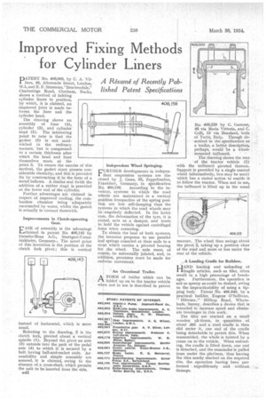
' An Occasional Trailer.
AFORM of trailer which can be folded up on to the tractor vehicle wheb not in use is described in patent
No. 406,229 by C. Garrone, 46 via Maria Vittoria, and C. Colli, 15 via Beaulard, both of Turin, Italy. Though described in the specification as a trailer, a better description, perhaps, would be a wheel mounted tailboard. • • The drawing shows the rear of the tractor vehicle (1) with the tailboard pivoted thereon. Support is provided by a single central wheel (alternatively, two may be used) which has a castor action to enable it to follow the tractor. When not in use, the tailboard is lifted up in the usual manner.. The wheel then swings about the pivot 2, taking up a position clear of the road and more or less under the rear of the vehicle. • A Loading Cradle for Builders.
HAND loading and unloading of fragile articles, such as tiles, often result in a high percentage of break
ages. Furthermore, the operation is not so speedy as could be desired, owing to the impracticability of using a tipping body Patent No. 405,646, by a practical builder, Eugene O'Sullivan,
" Hilltop Road, Whyteleaf e, Surrey, describes a device that is intended tc increase speed and eliminate breakages in this work.
The tiles are stacked on a small wooden plr tform, in quantities of about 350. and a steel cradle is then slid under it, one end of the cradle being detachable to permit this. When reassembled, the whole is hoisted by a crane on to the vehicle. When unloading, the cradle is lifted down, one end is detached, and the remainder is pulled from under the platform,' thus leaving the tiles neatly stacked on the required site, the operation having been performed expeditiously and without damage.