


New Combined Fuel-pump and Injector Unit
Page 50
If you've noticed an error in this article please click here to report it so we can fix it.
The Bellem, a French Device, which is Rocker-operated and Incorporates Certain Advantageous and Highly Ingenious Features
AN interesting fuel-injection system for oil engines, designed by a. French engineer, M. Sibert Bellem, 198, Rue Jean Charcot, Courbevoie, Seine, France, has now appeared in a revised form, in the latest system, the fuel pump and the injector are combined in a single apparatus, which apparently is giving satisfactory results.
Two important advantages of the Bellem device are its simplicity and the fact that its construction does not entail the extreme precision (0.01 mm. limits) required in certain pumps and injectors at present in ordinary use. A point in favour of combining the units is the elimination of the usual pipe lines carrying fuel at high pressure between pump and engine cylinders.
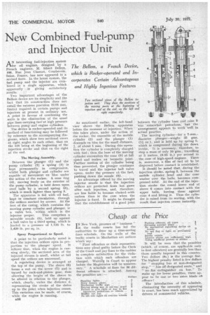
The device is rocker-operated and its method of functioning may be followed by reference to the accompanying dia grams, which show two sectional views at right angles to each other, that on the left being at the beginning of the injection stroke and that on the right at the end.
The Moving Assembly.
. Between the plunger (1) and the pump cylinder (2) a spring (3) is kept permanently in compression, whilst both plunger and cylinder are capable of movement en bloc under the action of the rocker. A cone ring (4), moving freely on the exterior of the pump cylinder, is held down upon steel balls by a second spring (5), which is much lighter than spring 3.
The apparatus is fed with -oil fuel, kept in constant circulation, through the orifices marked by arrows. At the foot of the casing, which contains the moving pump cylinder and plunger, is a valve box, within which is the
injector proper. This comprises a movable nozzle (8), held up against a ball valve by a third spring, which is loaded to a pressure of 1,136 lb. to 1,420 lb. per sq. in.
Spray Proportional to Speed.
A point to be particularly noted is that the injection orifices open in pro portion to the plunger speed. It follows that, when the engine is running slowly, the sectional area of the injected stream is small, whilst at full speed the orifices are uncovered.
A regulating device is arranged at the top of the pump. The sleeve (6) forms a nut on the screw (7) and is turned by rack-and-pinion gear, tints allowing the height of the sleeve to be altered in relation to the plunger, which, clearly, varies the distance d, representing the stroke of the sleive up to the point when injection ceases. This variation can be made, of course, while the engine is running.
1316 As mentioned earlier, the left-hand view shows the Bellem apparatus before the moment of injection. When this takes place, under the action of the rocker, the ensemble of the mobile cylinder (2) and the plunger (1) descends en bloc for the small distance, J, of about 1 mm. During this operation the cylinder Is completely charged with fuel ; then the base of the moving cylinder encounters the cone (9) at full speed and makes an hermetic joint. Further motion of the cylinder being thus prevented, the plunger continues to travel and the injector ball valve opens, under the pressure of.. the fuel, pushing down the nozzle (8). .
An advantage offered by the moving injector nozzle is that the injection orifices are protected from hot gases after each injection, and, therefore, are less liable to become choked 'with carbon than is the case when the injector is fixed. It might be thought that the establishment of a good joint between the cylinder base and cone 9 was somewhat precarious, but the arrangement appears to work well in actual practice. The moving Cylinder—for a 7-mm.diameter plunger—weighs 35 gms. (11 oz.), and is held up by spring 5, which is compressed during the down stroke. It is necessary, therefore, to stop a mass of only 35 gms., travelling at 3 metres (9.85 ft.) per second in the case of high-speed engines. There is, moreover, a film of fuel oil to be dispersed before contact is established.
It should be noted that, during the injection stroke, spring 5, between the mobile cylinder head and the cone washer over the balls, becomes compressed solid. At the end of the injection stroke the coned lower end of sleeve 6 comes into contact with the upper balls, forcing these against cone 4 and lifting it. Thus the cylinder is raised from its seating, with the result that injecton ceases instantly.