


Suction-operated Refuse Vehicle
Page 56
If you've noticed an error in this article please click here to report it so we can fix it.
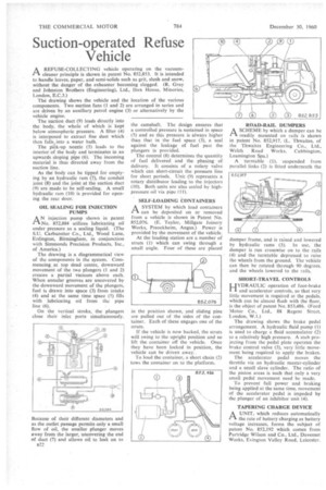
A REFUSE-COLLECTING vehicle operating on the vacuumr1. cleaner principle is shown in patent No. 852,853. It is intended to handle leaves, paper, and semi-solids such as grit, slush and snow, without the danger of the exhauster becoming clogged. (R. Gray and Johnston Brothers (Engineering), Ltd., Ibex House, Minories, London, E.C.3.)
The drawing shows the vehicle and the location of the various components. Two suction fans (1 and 2) are arranged in series and are driven by an auxiliary petrol engine (3) or alternatively by the vehicle engine.
The suction duct (9) leads directly into the body, the whole of which is kept below atmospheric pressure. A filter (4) is interposed to extract fine dust which then fallso into a water bath.
The pick-up nozzle (5) leads to the interior of the body and terminates in an upwards sloping pipe (6). The incoming material is thus directed away from the suction line.
As the body can be tipped for emptying by an hydraulic ram (7), the conduit joint (8) and the joint at the suction duct (9) are made to be self-sealing. A small hydraulic ram (10) is provided for opening the rear door.
OIL SEALING FOR INJECTION PUMPS
AN injection pump shown in patent M), 852,884 utilizes lubricating oil under pressure as a sealing liquid. (The S.U. Carburetter Co., Ltd., Wood Lane, Erdington, Birmingham, in conjunction with Simmonds Precision Products, Inc., of America)
The drawing is a diagrammatical view of the components in the system. Commencing at top dead centre, downward movement of the two plungers (1 and 2) creates a partial vacuum above each. When annular grooves are uncovered by the downward movement of the plungers, fuel is drawn into space (3) from intake (4) and at the same time space (5) fills with lubricating oil from the pipe line (6).
On the vertical stroke, the plungers close their inlet ports simultaneously.
Because of their different diameters and as the outlet passage permits only a small flow of oil, the smaller plunger moves away from the larger, uncovering the end of duct (7) and allows oil to leak on to B22 the camshaft. The design ensures that a controlled pressure is sustained in space (5) and as this pressure is always higher than that in the fuel space (3), a seal against the leakage of fuel past the plungers is provided.
The control (8) determines the quantity of fuel delivered and the phasing of delivery. It consists of a rotary valve which can short-circuit the pressuxe line for short periods. Unit (9) represents a rotary distributor leading to the injectors (10). Both units are also sealed by highpressure oil via pipe (11).
SELF-LOADING CONTAINERS
ASYSTEM by which load containers can be deposited on or removed from a vehicle is shown in Patent No. 852,076. (E. Taylor, Mitigate Joinery Works, Preockheim, Angus.) Power is provided by the movement of the vehicle.
At the loading station are a number of struts (1) which can swing through a small angle. Four of these are placed
'n the position shown, and sliding pins are pulled out of the sides of the container. Each of these engages one of the struts.
If the vehicle is now backed, the struts will swing to the upright position and so lift the container off the vehicle. Once they have been locked in position, the vehicle can be driven away, .
To load the container, a short chain (2) tows the container on to the platform. ROAD-RAIL DUMPERS
A SCHEME by which a dumper can be readily mounted on rails is shown in patent No. 852,917. (L. Thwaites, of the Thwaites Engineering Co., Ltd., Welch Road Works, Cubbington, Leamington Spa.)
A turntable (I), suspended from parallel links (2) is fitted underneath the dumper frame, and is raised and lowered by hydraulic rams (3). In use, the dumper is run crosswise on to the rails (4) and the turntable depressed to raise the wheels from the ground. The vehicle can then be rotated through 90 degrees, and the wheels lowered to the rails.
SHORT-TRAVEL CONTROLS I.JYDRAULIC operation of foot-brake and accelerator controls, so that very little movement is required at the pedals, which can be almost flush with the floor, is the object of patent No. 853,486. (Ford Motor Co., Ltd., 88 Regent Street, London, W.1.) The drawing shows the brake pedal arrangement. A hydraulic fluid pump (1) is used to charge a fluid accumulator (2) to a relatively high pressure. A stub projecting from the pedal plate operates the brake control valve (3), very little movement being required to apply the brakes.
The accelerator pedal moves the throttle via an hydraulic master-cylinder and a small slave cylinder. The ratio of the piston areas is such that only a very small pedal movement need be made.
To prevent full power and braking being applied at the same time, movement of the accelerator pedal is impeded by the plunger of an inhibitor unit (4).
TAPERING CHARGE DEVICE
A UNIT, which reduces automatically
the rate of battery charging as battery voltage increases, forms the subject of patent No. 852,192 which comes from Partridge Wilson and Co., Ltd., Davenset Works, Evington Valley Road, Leicester.