


Compression Adjuster for Oil Engines
Page 50
If you've noticed an error in this article please click here to report it so we can fix it.
A CCOR DING to F. Tippen, 3, Eastrtleigh Avenue, Earlsdon, Coventry, the usual manufacturing tolerances in connecting-rods, pistons and cylinder heads, whilst negligible from a mechanical point of view, are often sufficient to cause considerable differences in compression in a multi-cylindered oil engine. To correct this condition, this inventor proposes, in patent No. 495,218, to incorporate an adjustable wall in the combustion-chamber assembly.
In the drawing, the lower half of the chamber is machined out of the cylinder head, whilst the top is closed off by a screwed-plug assembly. This comprises the plug proper (4), forming the adjustable member, and an inner cup (2), which completes the chamber outline. The cup is fitted with a screwed tail (1), the nut of which serves to lock the plug in the set position.. The locking action is brought about by the compression of a soft dovetail-section washer (3) into contact with the wall of the bore.
New Injection-pump Governor.
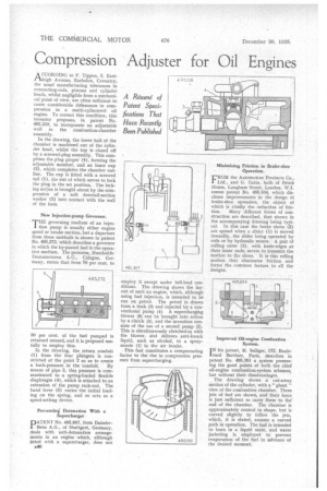
THE governing medium of an injection pump is usually either engine speed or intake suction, but a departure from these methods is shown in patent No. 495,272, which describes a governor in which the by-passed fuel is the operative medium. The patentee, HumboldtDeutzmctoren A.G., Cologne, Germany, states that from 70 per cent. to
80 per cent, of the fuel pumped is returned unused, and it is proposed usefully to employ this.
In the drawing, the return conduit (1) from the four plungers is constricted at the point 2 so as to create
a back-pressure in the .conduit. By means of pipe 3, this pressure is communicated to a spring-loaded flexible diaphragm (4), which is attached to an extension of the pump rack-rod. The hand lever (5) varies the initial loading on the spring, and so acts as a speed-setting device.
Preventing Detonation With a Supercharger
PATENT No, 492,857, from DaimlerBenz A.G., of Stuttgart, Germany, deals with anti-detonation arrangements in an engine which, although fitted with a supercharger, does not
A40 employ it except under full-load conditions. The drawing shows the layout of such an engine, which, although using fuel injection, is intended to be run on petrol. The petrol is drawn from a tank (3) and injected by a conventional pump (4). A supercharging blower (6) can be brought into action by a clutch (5), and the invention consists of the use of a second pump (2). This is simultaneously clutched-in with the blower, and delivers anti-knock liquid, such as alcohol, to a spraynozzle (1) in the air intake.
This fuel constitutes a compensating factor to the rise in compression pressure from supercharging. Minimizing Friction in Brake-shoe Operation.
FROM the Automotive Products Co., Ltd., and G. Gates, both of Brock House, Langham Street, London, W.1, comes patent No. 495,834, which discloses improvements in the design of brake-shoe spreaders, the object of which is chiefly the reduction of fric tion. Many different forms of construction are described, that shown in the accompanying drawing being typical. In this case the brake shoes (2) are spread when a slider (1) is moved inwardly, the slider being operated by rods or by hydraulic means. A pair' of rolling cams (3), with knife-edges at their inner ends, serves to transmit the motion to the shoes. It is this rolling motion that eliminates friction and forms the common feature to all the designs.
I N his patent, M. Seiliger, 172, Boule vard Berthier, Paris, describes in patent No. 495,291 a system possessing the good points of both the chief oil-engine combustion-system schemes, but without their disadvantages.
The drawing shows a cut-away section of the cylinder, with a "ghost " view of the combustion chamber. Three jets of fuel are shown, and their force is just sufficient to carry them to the end of the chamber. The chamber is approximately conical in shape, but is curved slightly to follow the jets, which, it is stated, assume a curved path in operation. The fuel is intended to burn in a liquid state, and water jacketing is employed to prevent evaporation of the fuel in advance of the desired moment.