


NEW TWO-STROKE ENGINE.
Page 32
If you've noticed an error in this article please click here to report it so we can fix it.
A Resumeof Recently Published Patents.
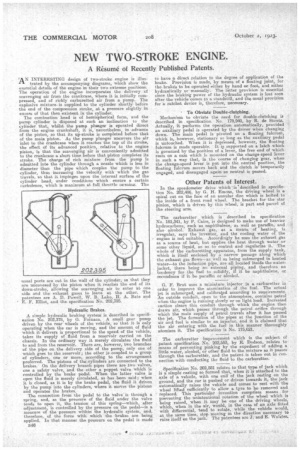
IA N INTERESTING design of two-stroke engine is illus trated by the accompanying diagrams, which show the essential details of the engine in their two extreme positions. The operation of the engine incorporates the delivery of scavenging air from the crankcase, where it is initially compressed., and of richly carburetted air from a pump. The explosive mixture. is supplied to the cylinder shortly before the end of the compression stroke, at a pressure slightly in excess of that then existent in the cylinder.
The combustion head is of hemispherical form, and the pump cylinder is disposed at such an inclination to the cylinder that, whilst the pump plunger is operated direct from the engine crankshaft, it is, 'nevertheless, in advance of the piston, so that its up-stroke is completed before that of the main piston. As the pump plunger uncovers the air inlet to the crankcase when it reaches the top of its stroke, the effect of its advanced position: relative to the engine piston, is that the scavenging air is conveniently admitted to the crankcase a short time before that piston completes its stroke. The charge of rich mixture from the pump is admitted into the cylinder through a nozzle which is less in diameter than the pipe which couples the pump to the cylinder, thus increasing the velocity with which the gas travels, so that it impinges upon the internal surface of the cylinder head, under conditions which ensure a certain turbulence, which is maximum at full throttle onsning. The
usual ports are cut in the wall of the cylinder, so that they are uncovered by the piston when it reaches the end of its down-stroke, allowing the scavenging air to enter at one side and the exhaust gases to leave at the other. The patentees are A. D. Powell, W. B. Lake, H. A. Bate and E. F. Elliot, and the specification No. 202,395.
Hydraulic Brakes.
A simple hydraulic braking system is described in specification No. 202,378, by G. 1■'ornaca. A small gear pump driven by the rear Wheels of the vehicle, so that it is only operating when the car is moving, and the amount of fluid which it delivers is proportional to the speed of the vehicle, takes its supply of fluid from a reservoir carried on the chassis. In the ordinary way it merely circulates the fluid to and from the reservoir. There are, however, two branches of the pipe on the delivery side of the pump, only one of which goes to the reservoir; the other is coupled to a group of cylinders one or more, according .to the arrangement preferred. the pistons of the cylinders are connected to the brakes. On the delivery branch pipes there are two valves, one a safety valve and the other a poppet valve which is controlled by the 'brake pedal. When the latter valve is open the fluid is merely circulated, as has been said; when it is closed, as it is by the brake pedal, the fluid ii driven by the pump into the cylinders, where it moves the pistons and operates the brakes.
The connection from the pedal to the valve is through a spring, and, as the pressure of the fluid under the valve tends to open it, the tension of this spring—which, after adjustment, is controlled by the pressure on the pedal—is a measure of the pressure within the hydraulic system, and, therefore, of the force with -which the brakes are being applied. In that manner the pressure on the pedal is made B46 to have a direct relation to the degree of application of the brake. Provision is made, by means of a floating joint, for the brake's to he operated either by hand or foot, and either hydraulically or manually. The latter provision is essential since the bralcirig power of the hydraulic system is lost soon after the vehicle comes to a standstill, and the usual provision for a ratchet device is, therefore, necessary.
To Obviate Double-clutching.
Mechanism to obviate the need for double-clutching is described in . specification No. 179,940, by R. de Stoutz. Actually, it, performs the operation automatically, provided an auxiliary pedal is operated by the driver when changing down. The main pedal is pivoted on a floating fulcrum, which is, however, stationary so long as the auxiliary pedal is untouched. When it is depressed, however, the floating fulcrum is made operable. It, is supported on a latch which is governed by the position of a. lever, the free end of which rests on a cam which is mounted on the change-speed lever in such a way that, in the course of changinggear, when the change-speed lever is put, into the neutral position, the floating fulcrum moves back. and the clutch is temporarily engaged, and disengaged again as neutral is passed.
Other Patents of Interest.
• In the speedometer drive which',isdescribed in specifiction No. 202,486, by G. H. Emons, the driving wheel is a spiral cut on the face of an annular disc which is bolted to the inside of a front road wheel. The bracket for the star pinion, which is driven .by this wheel, is part and parcel of the steering arm.
The carburetter which is described in specification No. 181,341, by P. Caire, is designed to make use of heavier hydrocarbons, such as naphthalene, as well as paraffin; and also alcohol. Exhaust gas, as a means of heating, is irregular, says the inventor, and the cooling water of the engine is not suitable. Accordingly he uses the exhaust gas as a source of heat, but applies -the heat through water or some other liquid, so as to control and regularize it. The whole of the carburetting apparatus, from the supply tank, which is itself enclosed by a narrow passage along which the exhaust gas flows—as well as being submerged in heated water—to the induction pipe, are all located inside the water. jacket, there being no external piping, and therefore no tendency for the fuel to solidify, if it be naphthalene, or recondense if it be paraffin or alcohol.
G. F. Brut uses a miniature injector in a carburetter in • order to improve the atomization of the fuel. The actual jet is submerged, and calibrated according to requirements. An outside conduit, open to the atmosphere, contains petrol when the engine is running slowly or on light load. IncreaSed suction clears this conduit through which the engine then draws air' which passes through the petrol orifice through which the main supply of petrol travels after it has passed the jet. The formation of the pipes at the junction of the air, and fuel is similar to an injector, and it is claimed that the air, entering with the fuel in this manner thoroughly atomizes it. The specification is No. 175,621.
The carburetter improvement which is the subject of patent specification No. 202,553, by E. Dodson, relates to means of preventing pinking by the expedient of adding a little water' alcohol, or other fluid to the mixture as it passes through the carburetter, and the patent is taken out in connection with conducting the fluid to the carburetter.
Specification No. 202,581 relates to that type of jack which is a simple casting so formed that, when it is attached to the axle of a vehicle, with one end of the jack resting on the ground, and the car is pushed or driven towards it, the jack automatically raises the vehicle and comes to rest with the wheel lifted sufficiently to allow a tyre to be removed and replaced. This particular invention comprises means for preventing the unintentional rotation of the wheel which is being raised, when it may he one of the driving wheels, which, when in the air, Would, in the case of an axle fitted with differential, tend to rotate, while the vehicle would, at the same time, stop moving in the direction necessary to raise itself on the jack. The patentees are J. and E. Walster.