


A Road-rail Transport System
Page 64
If you've noticed an error in this article please click here to report it so we can fix it.
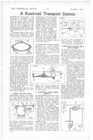
PATENT No, 657,513 shows a rapid method of transferring a road vehicle on to a rail truck. (Commer Cars, Ltd., Luton, Ulster Transport Authority, Belfast, and others.) The basic unit of the scheme is a semitrailer as used in conjunction with vehicles of the mechanical-horse type. For long-distance work the semi-trailer would be loaded on to a special railway truck.
The drawing shows a plan view of the rail-truck alongside the loading platform, with a semi-trailer in course of being loaded. .The rail-truck has a central well at a low level to receive the trailer. Part of the well floor is made in the form of a turntable .which can be swivelled so as to overlie the loading platform and form a bridge over which the semi-trailer can be run.
The semi-trailer is fitted with 'jockey wheels (1) which support it when away front its tractor, also forming the driving unit when it is to be swivelled on to the truck.. The semi.-trailer having been backed on to the truck by its tractor, the jockey wheels-are lowered leaving the condition shown in the drawing. A handle (2) is used to rotate. the jockey wheels and thus the semi-trailer is slowly drawn
on to the truck, where it is finally secured by latches (3).
The loading time is said to be within the normal stopping time for a passenger.train at a station.
A WHEEL FOR TWIN TYRES QTRENGTH, lightness and rigidity ara the virtues claimed for a twintyre wheel shown in patent No. 657,206 (Wingfoot Corporation, Akron, Ohio. U.S.A.). The design is said to be eminently suitable for fabrication from steel or aluminium forgin gs, castings or pressings.
In the drawing, one rim (1) is shown complete with detachable side-wall, this unit is not shown on the second rim (2).
A38 Extending from the hub are three
pairs of spokes (3 and 4) haying a 65753 circumferential length of approximately 90 degrees. These are pro.vided with pressed-up ribs to give strength, and are firmly welded to the hub member. They are also welded to each other where they meet on to a small diameter.
The outermost diameter is inturned to form a part-cylindrical portion (5) which is welded to its partner at point 6. The rims proper are centred by this cylindrical part and secure&by clamps (7) which bear. directly on the left-hand rim, and through a spacer (8) on the right-hand one.
A PNEUMATIC ENDLESS TRACK
PATENT No. 657,578, (Etablissements Sciences Techniques, Vaduz, Lichtenstein) shows a ne* scheme for an endless track. It is really a long pneumatic tyre, arranged to run over a pair of wheels.
The drawing shows a cross-section of one of several different types. In this case, the exterior face is provided with a tread pattern (1) whilst the interior surface has a continuous central rib (2) which centres the track on its Wheels, the latter being grooved to suit. As shown, the rib also contains the inflation valve, Although an inner tube is shown, it is in reality in one with the outer portion.
A SUSPENSION SYSTEM FROM NORWAY
A LEAF-SPRING suspension system operating without the usual shackles and pins is shown in patent No. 657,466 (A/S Strommens Vaerk
sted, Oslo, Norway). Instead of pivot pins, the spring is mounted on knife-edges and rollers, which require little if any lubrication.
The spring is mounted cantilever fashion, its central bracket being free to rock it point 1. The front end is held by a T-headed bolt (2) having knife-edges on both its head and its nut. The axle assembly is constrained to swing in an arc by links pivoted at point 3; these links are not interconnected across the frame, so that each wheel is independently sprung.
The axle assembly transfers its load to the spring via a pair of rollers (4) acting under the bottom leaf, and it will be seen that an increase in load moves the rollers to the left and in so doing shortens the effective length of the spring, This is mentioned as a highly desirable characteristic in a suspension system. The unit shown at 5 is a conventional shock-absorber.
LUBRICATION FAILURE SHUTS DOWN ENGINE
AMEANS for shutting down an oil engine to idling speed should the lubrication system fail, is dealt with in patent No. 657,304 (E. Pobjoy, 17, Park Hill Rise, East Croydon). The scheme is intended for agricultnral tractors and other vehicles prone to receive scant maintenance.
In the drawing, I is a governor and 2 the injection pump with its control rod. The two units are connected by rodwork working in conjunction with a bellcrank (3). The latter is slideable, 'being attached to a hydraulic piston (4) which normally is in the position shown. The piston is maintained in this position by the pressure of the lubricating-oil pump (5) against the force of springs.
Should the oil pressure fail, the bellcrank is moved to the left, an action which cuts down the fuel feed to the minimum necessary to keep the engine running. This permits the vehicle to be driven slowly to its base, but prevents any real load being applied. For starting purposes, means are provided to suspend operation of the arrangement.
If desired, the device can be provided with a means for giving visual indication that adequate oil pressure exists in the lubrication system.