


AXLE DESIGN FOR HEAVY VEHICLES.
Page 16
Page 17
If you've noticed an error in this article please click here to report it so we can fix it.
Methods Adopted to Distribute the Load and Driving Torque to Secure Long Life and Freedom from Trouble.
OF ALL the interesting constructional features of heavy vehicles, axles—chiefly rear axles--convey with the greatest force the impression that designers and manufacturers have arrived at a full realization of the necessary strength and lightness of the component parts of a chassis.
Axle troubles on the road are a source of great loss of time and of considerable expense. With the heavy
continuous use to which commercial vehicles are put and the constant tendency to overload, there comes a need for the very best and strongest construction when it conce-rns so vital a part as a front or rear axle.
The transmission of the power in the best way has also been carefully considered. The general tendency is to use worm drives, although a few examples—and very fine examples they are—of bevel driving can be pointed to—more especially in the rase of the lighter vehicles. In the heavier vehicles bevel drive is, in many successful cases, employed as part of a doublereduction gear.
Then, again, the question of gearing down is important: The usual type of bevel drive1. whether of the straight or helical tooth form, necessitates either a big crown wheel or a very small pinion if the necessary reduction is to be obtained. Some easement of these conditions is apparent in the case of the worm drive, although it must be remembered that a worm drive to be reversible must not be of too wide a ratio, otherwise exactly the same difficulty as to the size of the big member of the pair arises. This difficulty has! as we have said, been obviated in some cases by using a double-reduction gearing.
Double-reduction Axles.
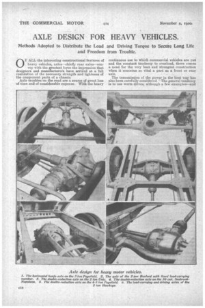
One examfile of this procedure is found in the case of the Pagefield 4-5 ton chassis, where the drive to the axle is taken acfoss the top of the axle proper and is transmitted by means of bevel gearing to the short back shaft which carries the differential gear, the gearing being by bevel pinion to the crewn wheel of the differential. This differential shaft, all enclosed in the rear casing, in turn transmits the power from small pinions at its ends to gearwheels at the ends of the torsion shafts of the main axle. In this way a very neat solution of the gearing-down problem is obtained. The front, of the Construction is extended in the form of an open tubular girder, at the forward end of which is located the universal joint the drive shaft, the front extension of the axle ca in forming a tongue member which is housed in spherical bearing in a deep, wide, arched cross me bar of the chassis frame construction.
In the 3 ton Pagefield a banjo-type of back axl with the banjo laid horizontally, is used, and a to direct worm drive is incorporated. This method give an extremely neat but very strong axle, particular car having been taken in the design to strengthen the ea ing at the point where it leaves the differential casin and emerges into the hollow axle ends. The axle i of the full floating type, with Timken roller bearing Another form of double-reduction axle, but on lighter model of construction, is the rear axle of th 2 ton Unic chassis. Here the cardan or propelle shaft, which is exposed, drives at its rear end pinion in a housing forming the front upper part o the differential casing. In this housing is situat also a larger gearwheel, meshed with the smalle wheel at the end of the carda,n shaft. This large -wheel is in turn geared, by the conventional hey pinion, to the crown wheel of the differential gea A torque member of pressed steel, with a laminat spring anchorage is used to take the turning strain.
Reduction at the Road Wheels:
Another system of reducing gear coniprises severa ingenious and differing examples, but,. in essence they are the same, in spite of minor details of lay-on and application.
This system incorporates, in all cases, a reduetio at the road wheels themselves by the utilization o internal toothed drums on the wheels driven by smal pinions at the ends of torsion shafts of a differentia gear, placed either in front or at the rear of, an parallel to, the main dead axle 'carrying the load.
An excellent example of this very sound construe tion is presented in the ease of the Hawkeye chassi of American origin. This is a 30 h.p. 2 ton job Here, a big curved axle, curved rearwardly, carrie the load and the spring plates, the wheels hemr! mounted on big hearings at its end. In front is th differential ease, and the side shaft tubes are integra and attached to the curved back axle. The ends o the side shafts carry pinions engaging with th internal teeth of the road wheel drums.
This method of construction has the twofold advantage of relieving the working axle of the loadand the road shocks, and allowing of a simple form of gearing down, while the differential gear and crown wheel gear, running at a higher speed than the axle, can be made correspondingly lighter and stronger and less bulky. The tooth load is lessened in direct ratio to the gearing down at the road wheels. Another example, embodying the same principle, but carried out in a different way, is the rear axle of the Burford chassis. Here the arrangement, the same in effect, is reversed. The differential gearshaft is placed at the back of the fixed axle on which the wheels run and the fixed axle is so formed that the front end' of the differential drive is housed through it and carries at the forward end the contracting foot brake. The rear differential shafts drive the road wheels by small pinions meshing with internal toothed drums. The construction provides for a very strong attachment of the differential casing to the rigid axle, and in a particularly neat manner, and gives ample anchorage for the rear brake.
In the Seabrook-Napoleon chassis yet another method of attaining the same end of a reduction of gearing at the axle is presented. Here the solid Hsection back axle is so built as to present at its forward face a base to which the differential gearbox is bolted, as seen in the illustration The rear axle is a ,complete solid construction, carrying the spring attachments and having the road wheels rotating on big roller bearings at the ends. The differential and side shafts (torsion) are independently carried in front, and drive, through the medium of pinions gearing with the internal teeth on the drums, the rear road wheels at a reduced speed.
Quite a number of the big vehicles have the inverted type of banjo or kettle-drum type of axle casing, with the worm drive crossing the top. A good example is shown in the case of the Commer Oar type 2G of two tons rating. Here an advance has been made as regards the method of taking the torque. The worm shaft, forward of the wenn, is carried in a propeller tube rigidly attached to the differential casing and anchored at the forward end in a spherical housing in a strong cross-member of the chassis frame. Inside this housing and axial with it Is the universal joint.
These examples, culled amongst numerous most interesting systems of construction, are presented as indicating, in a wide sense, the general tendency towards giving greater importance and care to the question of back axle construction.
Front Axles.
The problem of the front axle is not so intricate as that of the rear, bait, -nevertheless, it has by no means been shelved. The rigidity and strength necessary for the heavy duty imposed upon it in the case of continuous commercial ,service have not been lost sight of. One of the outstanding points of interest in this connection is the fact that the forked axle end is now very rarely used. The forked member, if, indeed, we may now term it forked, is now usually the stub axle, which generally has a good housing, well supported and shrouded sideways, for the solid end of the axle itself. Particularly good examples of this are found on the Brasier and on the Oaledon.
In 'only a few eases are tubular axles used. Generally, they are of deep, wide, H section, although many of the heavier vehicles are provided with of solid rectangular section. The tendency has been ,to strengthen the axle and to reduce the overhang of the stub axles as much as possible—the latter is a most important point, and capable of still further development, since it affects not only the strength and wearing properties of the articulation, but also is a matter which intimately affects the ease of steering, which is by no means a negligible factor in the operation of these heavy vehicles. The fatigue of long stretches of driving of a big truck whose steering is sluggish or heavy has to be experienced to be believed. es