


SCAMMELL'S MECHANICAL HORSE
Page 42

Page 43
Page 44
If you've noticed an error in this article please click here to report it so we can fix it.
now, in production
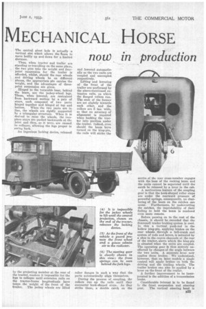
A 3-ton Articulated Five wheeler Incorporating Tractive and Trailing Units, Coupled by an Ingenious and Auto matically Operated Mechan ism. A 10 h.p. Engine Gives a Cruising Speed of 24 m.p.h.
0 N its original introduction at the Scottish Show in November last, the Scammell Mechanical horse, as it is desiguated by its maker, Scammell Lorries, Ltd., Watford, aroused considerable interest. Since that date, however, the early design has been considerably improved, an extension of the Scammell works has been built and equipped for its manufacture at the estimated rate of 25 per week, aud, in its latest form, the machine is now in full production.
With a performance that is really remarkable, an adaptability for the class of work that is regarded by many as best carried out by the horse, and a first cost of about f 300, it seems a most attractive proposition and should attain much popularity. Besides hauliers, its appeal extends to railway companies, for use at goods depots, for example, and to those engaged in almost every industry now employing either horses or motor vehicles for transport. Types of carrier to suit special requirements can be provided.
The outfit is an articulated fivewheeler steered by a single front wheel and propelled by the two rear wheels of the tractive unit, which is detachably coupled by an extremely clever piece of mechanism to a trailing unit having a load capacity, in the present model, of 3 tons. Larger models to carry 5 tons and 6 tons will also be available.
Unquestionably, the most interesting feature, the turntable and coupling
gear, deserves first description. Capable of being disconnected and connected up again almost entirely automatically and in as little time as it takes to drive the tractor away from the trailer and reverse it into position again, the
B24 mechanism has been designed to give complete security, limited flexibility in two planes and simplicity of operation.
The turntable follows the general design of the well-known large, articu lated Scammell lorries. Below it, a rocking beam is pivoted at the centre. On each end are flanged rollers. To right and left of the pivot in the turntable body are pins set at right angles to the beam, which is provided with slots on its upper edge to receive them. The central pivot bole is actually a vertical slot which allows the team to move bodily up and dawn for a limited distance.
Thus, when tractor and trailer are standing or travelling on the same plane, the two pins take the weight and fourpoint suspension for the trailer is afforded, whilst, should the rear wheels and driving wheels be on different planes, the appropriate pin carries the weight, and the advantages of threepoint suspension are given.
Hinged to the turntable base, behind the beam, are the jockey-wheel legs. These, when lowered, are restrained from backward motion by a pair ef stays, each composed of two parts hinged together and hinged at top and bottom. When the two parts are in line, the wheels are rigidly supported by a triangular structure. When it is desired to raise the wheels, the twopiece stays are pushed backwards at the joint and thus, as it were, are caused to collapse, allowing the legs proper to swing back.
An ingenious locking device, released by the projecting member at the rear of the tractor, renders it impossible for the legs to collapse until extension rails on the tractor-frame longitudinals have taken the weight of the front of the trailer. The jockey wheels are lifted and lowered automatically as the two units are coupled and uncoupled. respectively.
Lifting and lowering of the front of the trailer are performed by the above-mentioned extension rails, on which the flanged rollers run. The ends of the former are set slightly towards each other, and the rollers are 5 ins, wide, so that no accuracy of alignment is required when backing the tractor into position under the trailer. Indeed, even should the 'beam have turned on the king-pin, the rails will strike tho roller flanges in such a way that the parts automatically align themselves.
During the process of coupling, the rollers run up the rails until they encounter hook-shaped stops. As they strike these, a double catch on the centre of the rear cross-member engages with the base of the rocking beam and the units cannot be separated until the catch be released by a lever in the cab.
A meritorious feature of the coupling gear is that the hook-shaped roller stops are under the rearward pressure of powerful springs, consequently, no chattering of the beam on the catches can occur. Furthermore, by undercutting the catches, the improbability of their failing to hold the beam is rendered even more remote.
Before passing on to the rest of the chassis, it should be recorded that the Scammell trailer-braking system is used. In this a vertical push-rod in the hollow king-pin, applying brakes on the rear wheels through a bell-crank and system of rods and levers, is actuated by a shoe in the centre channels at the rear of the tractor, above which the king-pin is situated when the units are coupled. The operating gear is thus entirely unaffected by changes of the angle between the two units. A separate lever now applies these brakes. We understand, however, that on later models a single control will apply brakes on both the driving and the trailing wheels. The trailer brakes can also be applied by a lever on the front of the trailer.
A further improvement to be incorporated is the addition of a transmission brake.
Considerable interest is to be found in the front suspension and steering gear. The vertical steering head is mounted in the centre of the front crossmember, which is of stout sheet metal, welded and of box construction, the weight being taken by a ball-thrust race at the top. The fork is a heavy forging, to the bottom ends of which approximately horizontal arms are pivoted at their front extremities.
Close behind the pivot points, the front axle acts as a brace between the two arms to lugs on which it is strongly bolted. 'Between the rearmost end of each arm and the corresponding , fork leg is a coiled compression spring which carries the weight. A damping device is contained in the boxes in which the pivot pins are also housed. A skew gear transmits motion from the steering wheel to the fork assembly, the reduction being such that two and a quarter turns of the steering wheel move the front wheel from lock to lock, that is to say, an angular motion, limited by stops to rather less than 180 degrees.
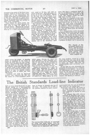
Designed and built by Scammell Lorries, Ltd., especially for this job, the engine is a four-cylindered petrol unit, rated at 10 h.p., and with an output of 20 b.h.p. Bore and stroke are 2i ins. by 3i ins. (1.137 litres). Placed on the near side of the frame, it is started by hand through a pinion meshing with the camshaft wheel end situated above it, the object being to ' afford a position for the starting handle at a convenient height above the ground.
The cylinders and upper half of the crankcase are one casting, whilst the head is detachable. 'To allow ample .ground clearance, the oil sump is bolted to the side of the engine base, a steel frame affording it protection from damage. The accessibility of the filler, through which an indication of its con. tents can be gained, should be noted. ;A Side valves are used as well as a Three-bearing crankshaft with forced lubrication to the big-ends, the pump being submerged and driven from the bottom end of the distributor shaft
which passes through the block and head, affording a most accessible position for this item of the coil-ignition system. Special care has been taken to ensure adequate lubrication for the high starting handle-shaft bearings.
Engine and gearbox form a unit, the whole being suspended on rubber at three points. The four forward ratios are : 1, 1.75, 3.02 and 6.17 to 1, reverse being 8.19 to 1, whilst the doublereduction back axle, which is a Kirkstall component, gives an overall ratio of 10.28 to 1. With 8.25-in. by 10-in. tyres, this gives a maximum speed in top, we are informed, of 32 m.p.h., and a recommended cruising speed of 24 m.p.h. The trailing wheels are shod with 34-in. by 6-in. tyres.
The frame is composed of two main longitudinals, straight for the most part of their length, the dimensions at midpoint being 6 ins. by 2 ins. by 146 in. There are three main cross-members. An 8-gallon petrol tank is mounted over the radiator. Water circulation is on the thermo-siphon system, cooling being by a fan belt driven from the startinghandle shaft.
At a demonstration of the Scammell Mechanical Horse given from the works last Friday, we witnessed the vehicle laden to the extent of 2i tons, repeatedly coupled and uncoupled, with a rapidity and ease that were almost uncanny, driven up and down a hill having a gradient of about 1 in 7, reversed up the same gradient, turned in a 15-ft circlethe road was only 18 fr. wide from bank to bank and there was room to spare on either side—and its manceuvrahility most convincing manifested.
To say that we were favourably impressed by its performance is a mediocre expression of our opinion. In so far as our observations are coucerned, we can vouch for the sincerity of its maker's claims. Its petrol consumption is said to be 16 m.p.g., its tax is 125, its main tenance cost should be moderate.