


Patents Completed.
Page 24
If you've noticed an error in this article please click here to report it so we can fix it.
VARIABLE-SPEED GEAR.—Fowler and Another.—No. 10,853, dated 7th May, 1909.—This invention relates to variable speed gear and is specially applicable for road locomotives. It has for its object to prevent two sets of gears from being moved either partially or wholly into engagement simultaneously.
This is effected by controlling two sets of gears from a rotary shaft having arms or cranks which are connected by suitable levers to the sliding gears. The cranks on the rotary shaft are so disposed that, when the shaft is turned in one direction, one set of gears is brought into engagement while the other set is not moved to any appreciable extent, On the shaft's being turned in the opposite direction, the gears in engagement are first disengaged and the second set of gears is then brought into operation. A third set of gears is controlled by a second rotary shaft, having only a single crank which operates in a similar manner. The two rotary shafts are con. trolled by two pivoted locking levers in such a manner that neither of the rotary shafts may be turned unless one of them is in such a position that the gears controlled thereby are disengaged.
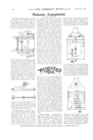
ORA NCE -SPE ED GEAR—Renault. —No. 10,108, dated 28th April, 1909— This invention relates to hydraulic transmission gear, in which there is combined a clutch and a progressive change-speed gear. The driving shaft, is shown at the left-hand side of the illustration, and carries a collar which, while compelled to rotate with the shaft, is free to be inclined thereon ; suitable links and sliding gear are provided for this purpose. Rotatable on this collar, is a ring which has rollers on its periphery that engage internal projections or run-ways on the casing. This ring is connected by means of rods to a number of plungers which work in cylindrical chambers formed in an annular member. which is connected to the casing so as to rotate therewith, but is free to move
longitudinally. This annular member is forced by means of springs against a distributor disc, which is carried by and rotates with the driving shaft. The rotating distributor disc bears against a distributor plate which is integral with the driven shaft and is also rigid with the casing. Bearing against the opposite face of the distributor plate, is another annular member in which is formed a number of cylinders having reciprocating plungers that are connected to an inclinable ring, which is similar to the ring mounted on the driving shaft, except that it. does not rotate. Suitable gear is provided for varying the inclination of this second ring. When the ring on the driving shaft is pernendicular to the latter, the pumps will he inoperative, and, therefore, no drive will take place, this being the " free " positicn. When. however, the ring is inclined, as shown in the illustration, the ramps at once start working and force fluid to the cylinders on the driven side of the rear, and, owing to the resis
tance of the driven portion of the pumping gear, the casing will be rotated by the ring on the driving shaft. This has the effect of causing the plungers in the cylinders of the driven portion of the gear to commence reciprocating, and the speed that the driven shaft assumes is auch that the volume of fluid supplied by the pumps of the first, system is equal to the volume absorbed by the driven portion of the pumping system. When the ring on the driven side of the gear is perpendicular to the driven shaft and the ring on the driving shaft is inclined thereto, the drive is direct owing to the ring on the driving ehaft becoming locked with the casing. It will be seen that. by varying the inclination of the two rings, progressive speeds can be obtained, starting from " free engine " up to direct drive. A modification is dealt with in which the mechanism is so ar ranged that the variation of the speed of the driven shaft relatively to that of the driving shaft can be effected automatically according to the variation of the resistance opposed by the driven shaft.
EXCESS SPEED INDICATOR.— Marley and Another—No, 9,319, dated 20th April, 1909.—This invention relates to excess-speed indicators of the type in which, on a predetermined speed's being exceeded, governor weights are caused to operate a hammer which latter sounds a gong or other similar device. The indicator is driven from the road wheel by means of a flexible shaft which is coupled to a square shaft mounted in ball bearings within the indicator, A roller is mounted so as to be slidable on the square shaft and is adapted to be moved radially across the face of a disc, which latter carries the governors. It will be seen that, by adjusting the position of the roller on the disc, the speed of the latter can be regulated and, consequently, the speed at which the device operates may be varied as required. The adjustment of the roller is effected by a screw which engages a forked member that carries the roller. This forked member is also connected to a sector having a number of coloured glass windows that arc adapted to be moved in ftont of a lamp to indicate the position of the roller. The sector is in turn connected to a pointer which moves over a graduated scale.