


BRAKE MECHANISM.
Page 30
If you've noticed an error in this article please click here to report it so we can fix it.
A Resume of Recently Published Patents.
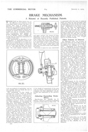
THERE CAN be little.doubt that, as the efficiency and reliability of the front-wheel brake is more and more improved, and, what is perhaps more important, as confidence in it increases, it will be adopted to a greater extent in connection with commercial vehicles, particularly on chassis which are mainly intended for use as passenger vehicles. This circumstance lends interest to patent specification No. 180121, by A. L. F. Wattel, which is chiefly concerned with an improved construction of a brake of this type.
The construction is described, in the specification, in alternative forms—one, in which it is mounted on the pivot of a front axle in which the TEM is solid with the axle proper; the other, in which the jaw is in one with the..stub, and moves with it. The difference is one of detail only. We need concern ourselves only
with one method of application, and we will consider that in which the jaw is integral with the axle
The mechanism of 1the brake is mounted on a stud, which is screwed into the top of the jaw, so that it is in line with the pivot itself. Thn construction compares with a former one, in which a cam mechanism, so mounted, operated a lever on which was carried the brake expander. In the present design this intermediate mechanism 'is eliminated, this simplifying the gear, reducing the coat of manufacture as well as the number of parts liable to wear.'
The stud, to which we have already referred. carries a horixontal lever, which is operated, through the medium of a cable or coupling rud, by means of the usual pedal or hand lever, or other means. The boss of this lever is in the form of a cam, and as the lever is moved, thecam lifts a. part which is mounted -on the stud, above it. The lever is freely rotatable on the stud ; the other pert is prevented, by splines or other method from rotating. The part which is lifted is slightly cenical as to its outer ev14 and upper surface, the degree of taper depending on the leverage of the brake mechanism, and also on other considerations which will occur to the designer. As it is lifted, this conical portion, which is in permanent contact with rollers on the outer ends of the expanding brake shoes, pushes those rollers apart, and with them the brake shoes, thus applying the brakes.
Provision is made for easy adjustment of the depth of engagement of the cone with the rollers, and several methods of arranging for that adjustment are described and illustrated in the specification.
Adjusting Expanding Brake Shoes. '
Specification No. 179,5.33, by E. Buisson, refers to a method of adjusting expanding brake shoes as they wear. It is concerned with that type of brake in which the shoes are each provided with a projecting rod, the end of which bears on the common pivot, or fulefum, of the shoes. Adjustment of the shoes is possible, in this type, by lengthening or shortening the red. In the construction, which is described; these rods at their innet ends, bear on the eccentric portions of setscrews, which are put into the shoes from the side and are accessible for turning, and thus varying the effective lengths of the rods, through holes in the brake casings.
Other Patents of Interest.
An ingenious valve, the purpose, of which is to allow the more efficient use of the engine as a brake, is described in specificaeort No. 189,052, by A. Hulamann. Apparently it is intended that this valve should be placed in communication with one of the engine cylinders. The valve itself has three openings. One goes to the cylinder' the communication in that case being by a suitable pipe. The other two are to the atmosphere: one is closed by an automatic, springcontrolled valve of familiar construction; the other is a screw-down valve of peculiar formation. When the screwdown valve is right down, it holds the automatic valve shut, and at the same time closes the other opening to the atmosphere. So set. the valve is entifely
inoperative. Slight withdrawal of the screw-down valve frees the automatic valve, and also completely opens the other passage. In that position, the cylinder draws air from both passages, but expels it only through the second one, as the automatic valve acts of course, as a non-return valve. This allows the engine to run fairly freely. Further withdrawal of the screw-down valve partially closes the second passage, and thus increases the back pressure in the cylinder.
An improvement in the method of lubricating road-wheel hubs is described in specification No. 188,965, by T. Blackwood Murray and the Albion Motor Car Co., Ltd. There are two annular reservoirs for lubricant, one at each Mid of the hub. One is slightly smaller than the .other, as regards its outer circumference, and the two are .connected by pipes or tubes, so that the effect is constantly, as the result of centrifugal force, to return any oil from the smaller to the larger. Oil is fed to the larger chamber, so that constant circulation of the oil is ensured.
A flexible disc coupling, the design of which facilitates rotational adjustment of the two shafts Which: it connects, is the subject of patent specification No. 189,030, by W. Riley. Specification No. 188,711, by H. R. Ricardo, refers back to an older patent by the same inventor. It deals with a method of transmitting the power from a pair of side-by-side engines to a common eentrallv disposed shaft. A simple form of fastening for a valve spring collar Ls described in No. 188,967, by E. Jerome. A &odes:, carburetter, in which the flow of petrol is controlled by engine section, acting on floating valves, is described in lie. 188,704, by E. L. Sinipsori: