


Improved Injection-pump Delivery Valve
Page 48
If you've noticed an error in this article please click here to report it so we can fix it.
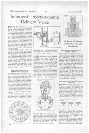
DATENT No. 513,349 comes from
Bryce, Ltd., and G. Green, both of Kelvin Works, Hackbridge. The subject is an improved form of delivery valve for injection pumps. Referring to the drawing, the valve itself consists of a sliding body (2) with a conical nose, held on its seating by a spring (5). When the fuel pressure rises, the valve is lifted from its seat and allows a small amount of fuel to pass via the small holes (3). These, however, can'not deal with the whole amount, and the valve body is, therefore, forced higher until the close-fitting 'rim (4) is clear of the bore, after which the fuel can freely pass.
At full output the valve is lifted far enough to lift a heavily spring-loaded washer (1), and it is this extra loading that provides an instant release at the end of injection. The full line pressure is not maintained after injection, however, as the leaks (3) allow the pressure to fall to a value .dependent upon the weaker spring (5). This feature reduces the possibility of dribble, without unloading the pipe-line to an unnecessarily low value that would have to be built up on the next injection stroke.
TRACTOR WHEEL WITH RETRACTABLE STRAKES
T° provide, at the will of the driver, a non-slip drive for a pneumatically tyred tractor is the object of a device shown in patent No. 513,519 by H. Dixon, Fordington, Great Ayton, Yorks. To the side of the tyred wheel is attached an extra metal rim of which the diameter is less than that of the tyre. Slots in the rim form guides for a number of slidable spoke-like strakes attached at their inner ends to a disc. The last-named can be moved through a small angle, the effect of which is to move the strakes to a larger or smaller diameter.
In the position shown they are retracted, but if the disc be turned they move from a tangential to a radial position and, in doing so, project beyond the tyre. The patent also deals with automatic mechanism for altering the position while running..
FRENCH ROTARY-VALVE DESIGN ANEW rotary valve is shown in patent No. 512,052 (void) by P. Couillaud, Route de Chauvigny, Poitiers, France. The novelty in this design is that the cylinder block is not fixed to the crankcase, but is resiliently urged upwards to make a seal against the rotary valve.
Referring to the drawing, the rotary valve (I) is carried in rigid bearings supported by uprights from the crankcase. The ports in the valve alternately connect the combustion space with the inlet and exhaust ports in known manner. The cylinder block, with its upper half-bearing (2), is guided by sliding supports and is urged upwardly against the valve barrel by a single spring-loaded bell-crank (3). This not only presses the cylinders upwards, but also imparts a side pressure on to the guide faces. The valve barrel is internally water cooled.
IMPROVED SUCTION SPARKTIMING CONTROL
control the ignition timing by
means of the intake suction is the aim of a device described in patent No. 513,142 by Carter Carburetor Corp., St. Louis, Missouri, U.S.A. The drawing shows a section of the carburetter, which is of the down-draught type, and the ignition distributor, the latter being moved by a suctionresponsive diaphragm (1).
The diaphragm is connected to an elongated port (2) in the induction tube; this port is half-covered in the idling position, so that full suction reaches the diaphragm, giving full advance for idling. When the throttle is opened slightly, the spark is retarded, but is gradually re-advanced as the. engine speed and load rise.
NEW METHOD OF FIXING BRAKE FACINGS nODERN assembly methods call for IVigreat accuracy in the dimensions of brake-shoe facings, a condition not always satisfied by the usual methods of attachment. An improved system is shown in patent No. 513,331 by G. Roberts and Bendix, Ltd., King's Road, Tyseley, Birmingham.
It is proposed to unite the friction material and the shoe permanently by die-casting. The shaped facing is placed in the mould, and the molten metal (zinc-base alloy) is poured in. The heat of the metal performs the additional duty of " curing" the friction material.
The drawings show three suggested sections for the keying means, a dovetail (A), a rivet-like series of studs (B), or a set of plain pins (C), which extend to the outer face of the facing.