A Tipping Gear Improvement.
Page 55

If you've noticed an error in this article please click here to report it so we can fix it.
TN the new design for end-tipping gears with long screws, 'recently brought out by Walters and Co., of Albert Street, Rugby, an interesting form of construction has been adopted.
The trouble with some gears with screws in which lateral movement is present has been that, when unloading on rough ground, the chassis distortion often caused by the uneven surface, or as a consequence of uneven distribution of the load, has resulted in locking or stiff working of -the screw and lifting nut.
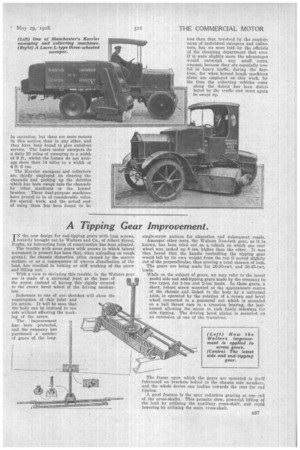
With a view to obviating this trouble, in the Walters gear rise is made of a Universal joint at the base of the screw, instead of having this rigidly secured to thecrown bevel wheel of the driving mechanism.
Reference to one of our sketches will show the construction of this joint and its action. It will be seen that the body can be inclined to one. side without affecting the working of the screw.
The improvement has been protected, and the company has purchased anumber of gears of the long
single-screw pattern for alteration and subsequent resale.
Amongst other tests, the Walters Non-lock gear, as it is known, has been tried out on a vehicle on which one rear wheel was jacked up 8 ins, higher than the other. It was then found that the handle controlling the tipping gear would fall by its own weight from the top if moved slightly out of the perpendicular, thus proving a total absence of lock.
The gears are being made for 20-30-cwt. and 30-45-cwt. loads.
While on the subject of gears, we may refer to the latest model side and end-tipping gears made by the company in two types, for 1-ton and 2-ton loads. In these gears, a short, robust screw mounted at the approximate centre of the chassis and linked to the body by a universal joint, is operated by the rotation of a crown and bevel wheel connected to a gunmetal nut which is mounted on a ball thrust race in a trunnion bearing, the lastnamed allowing the screw to rock freely sideways for side tipping. The driving bevel pinion is mounted on an extension of one of the trunnions.
The frame upon which the gears are mounted is itself ' fulerumed on brackets bolted to the chassis side members, and the whole device can incline towards the rear for end tipping.
A good feature is the spur reduction gearing at one end of the cross-shafts. This permits slow, powerful lifting of the load by utilizing the auxiliary cross-shaft, and rapid lowering by utilizing the main cross-shaft.


